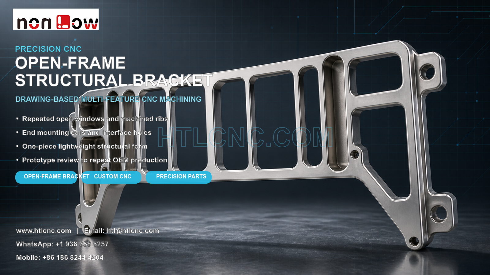
Open-frame structural bracket custom CNC machining coordinates repeated windows, thin load paths, mounting ears and interface holes in one lightweight part for prototype and repeat OEM supply.
Open-frame structural bracket custom CNC machining is relevant when an OEM assembly needs one lightweight part to combine repeated open windows, narrow connecting ribs, end mounting ears and multiple interface holes. The pictured component visibly has a long one-piece frame, a sequence of rectangular openings, narrow vertical webs, larger end windows, projecting mounting features and holes approached from different faces. HTL CNC provides custom CNC machining, precision CNC parts, drawing-based OEM manufacturing, prototype validation, low-volume production and repeat supply for overseas engineering and procurement teams. The image does not establish material grade, tolerance, load rating, finish or final application; those requirements must come from the customer's released drawing, STEP model and assembly information.
What Makes an Open-Frame Bracket Difficult to Machine?
Removing material to create multiple windows changes the stiffness of the workpiece throughout the cycle. Long edges and thin webs may react to cutting force, heat and clamping pressure differently after roughing. A machining plan therefore needs to consider stock support, roughing sequence, remaining material and when the final profiles should be finished.
The frame also combines broad planar relationships with local holes and pockets. A part can appear visually correct while window position, rib thickness or mounting-hole relationships fall outside the drawing. Process planning should begin with the functional interfaces rather than with the most convenient tool path.
Datum Strategy for Repeated Windows and End Interfaces
The buyer should identify which surface locates the bracket in the assembly, which end establishes length and which holes control orientation. From those datums, the supplier can relate the repeated windows, outer profile, end ears and local interface holes to a common coordinate system.
If a hole or counterbore is machined after refixturing, the setup plan should state how the primary datums are transferred. Indexed multi-axis machining may reduce transfers when geometry and volume justify it, but axis count alone does not guarantee positional accuracy. A stable datum scheme and verified setup remain the controlling factors.
Rib Thickness, Corner Radii and Open-Window Geometry
Repeated windows create multiple ribs whose thickness and spacing may affect weight, stiffness and assembly clearance. Drawings should define the dimensions that are functionally controlled, including window width and height, internal corner radii, web thickness, edge distance and profile tolerances where required.
Internal radii should be compatible with practical cutter sizes unless a sharper corner has a documented function. Larger, more rigid tools can improve consistency and tool life. When adjacent windows leave narrow webs, balanced material removal and controlled finishing passes help limit local distortion.
Mounting Ears and Multi-Face Hole Features
The visible end features include projecting ears and holes on different orientations. An RFQ should distinguish clearance holes, threaded holes, counterbores, locating holes and noncritical access holes. Thread standard, engagement, depth, chamfer and post-finish acceptance should be explicit.
Where a side hole intersects a window or another passage, deburring and chip removal must be planned from both directions. The inspection plan should also state whether hole position is measured from the main frame datums, from a local boss or from a mating interface.
Inspection Evidence for Supplier Qualification
A risk-based inspection plan can cover overall profile, datum flatness, repeated-window location, web thickness, end-ear position, hole size and position, threads, surface condition and drawing-defined geometric controls. Appropriate methods may include calibrated hand gauges, height measurement, optical inspection, CMM measurement and functional checking with a customer-approved fixture or mating part.
For B2B supplier onboarding, customers may request first-article data, material records, finishing documents and lot-level inspection reports. The record set should identify part number, drawing revision, purchase order and production lot so repeat orders can be traced to the released specification.
Surface Finishing Without Losing Functional Relationships
The metallic appearance does not confirm any specific material or finish. Depending on the confirmed alloy and service environment, a customer may specify anodizing, plating, passivation, blasting, polishing, painting or another treatment. Masked zones, threaded features, datum faces and coating-sensitive fits should be marked on the drawing.
Open frames also have many exposed edges. Edge-break requirements should protect handling and assembly while preserving intentional sharp reference features. Packaging should separate parts and protect mounting ears, thin webs and finished faces from contact damage during export shipment.
Prototype Validation to Repeat OEM Production
Prototype builds should confirm fit with the intended mating components, fastener access, cable or mechanism clearance and the relationship between end interfaces. If loading matters, the OEM is responsible for defining the engineering validation method and acceptance criteria; no load capacity should be inferred from the photograph.
After approval, controlled programs, qualified fixtures, first-piece inspection, tool-life monitoring and formal revision control support repeat-order consistency. HTL's prototype and low-volume CNC machining service provides a staged path from engineering samples to pilot quantities, while its custom CNC machining service supports recurring drawing-based manufacturing. 5-axis CNC machining can be evaluated when multi-face access or setup reduction provides a documented benefit.
RFQ Package for an Open-Frame Structural Bracket
Send the released 2D drawing and STEP file with material, prototype and production quantities, annual demand, functional datums, critical window and rib dimensions, hole and thread definitions, tolerances, surface treatment, inspection-document scope, validation requirements, packaging, destination and target delivery. Include mating-part data when it controls the end ears or interface holes. HTL CNC can then review manufacturability, inspection coverage and the supply plan for the actual open-frame structural bracket custom CNC machining project.
Website: www.htlcnc.com Email: htl@htlcnc.com WhatsApp: +1 936 358 5257 Mobile: +86 186 8244 4204
Have a part ready for engineering review?
Send your drawing, STEP file, material and quantity directly to HTL CNC for a manufacturing quotation.