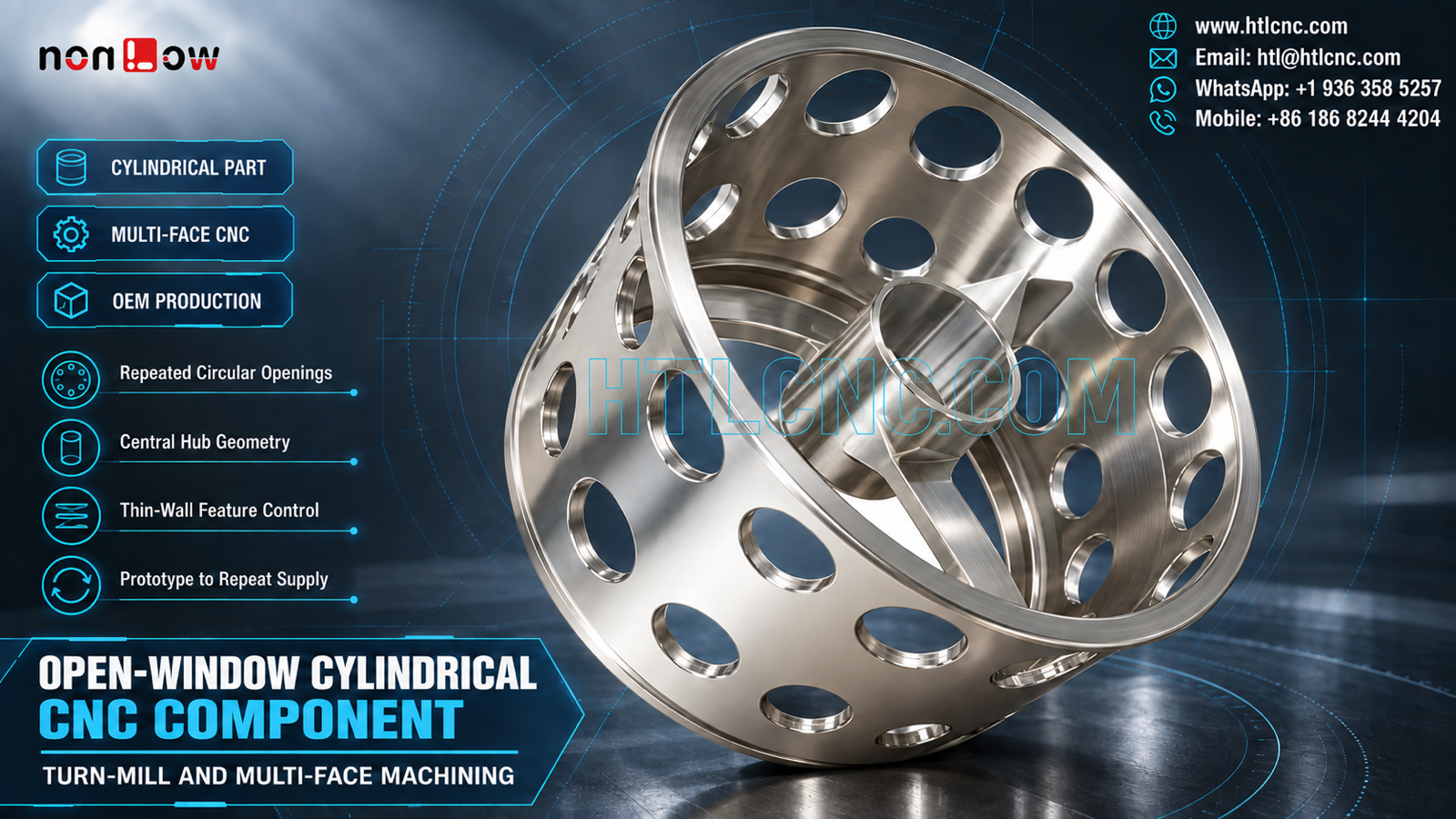
An open-window cylindrical CNC component combines repeated circular openings, a central hub, thin-wall geometry and multi-face relationships that require drawing-led machining and inspection.
An open-window cylindrical CNC component can combine rotational geometry with repeated milled features in one part. The pictured component visibly includes a broad circular rim, an open cylindrical wall, repeated circular openings, internal supports and a central hub or shaft-like feature. The image does not establish the material grade, heat treatment, surface finish, tolerance, load case, operating speed or final application. Those requirements must come from the buyer's released 2D drawing, STEP model and technical specification. HTL CNC supports overseas OEMs, product-development teams, equipment builders, engineers and procurement groups with drawing-based custom machining, prototype validation, low-volume production and repeat supply.
Start with the Functional Axis and Mating Interfaces
A cylindrical appearance does not by itself define the most important datum. The engineering review should identify whether the central hub, outer rim, an end face or another feature establishes the functional axis. It should also identify which surfaces locate the component in its assembly and which dimensions control clearance, concentricity or runout.
When available, the RFQ should include mating models and assembly orientation. This lets the supplier review tool access, fixture support and inspection reach without guessing the product's purpose. HTL's custom CNC machining service uses the released drawing and functional relationships as the basis for process planning.
Repeated Circular Openings Change Part Stiffness
The repeated circular openings are prominent visual features, but their diameter, spacing, quantity and function cannot be confirmed from the image. The drawing should define each opening or the governing pattern, edge breaks, positional tolerance and relationship to the selected cylindrical datum.
Removing material from a cylindrical wall can reduce stiffness as machining progresses. A process route may retain support during roughing, distribute cutting forces and finish sensitive features after a stable reference has been established. The actual sequence depends on wall thickness, material, stock form, tolerance and quantity. Thin-wall feature control should be validated from measurement data rather than assumed from nominal tool paths.
Central Hub Geometry and Circular Datum Control
The visible center includes a hub or shaft-like feature connected to internal supports. The buyer should specify diameters, lengths, shoulders, bores, threads or fits using the released drawing. If this feature shares an axis with the outer rim, the drawing should state the required runout, concentricity or position control using the applicable standard and datum framework.
Machining critical circular features in a common qualified setup can reduce datum-transfer error where geometry permits. Where refixturing is required, the process should use repeatable locating surfaces and verify that the hub, rim and end faces remain related to the drawing coordinate system.
Turn-Mill or Multi-Face CNC Machining?
The rotational surfaces may suit turning, while circular windows, internal supports and local features may require milling. Depending on part size, feature access, tolerance and production volume, a route may use CNC turning plus controlled milling setups, live-tool turn-mill machining, indexed 4-axis work or 5-axis CNC machining. The machine-axis count should follow the actual drawing rather than a marketing assumption.
HTL's CNC turning and turn-mill machining service can be reviewed when maintaining a shared circular reference across turned and milled features is important. A multi-machine route can also be appropriate when transfer datums, fixtures and in-process checks are clearly defined.
Tool Access, Internal Supports and Edge Condition
The open structure exposes internal regions but may still create long reach, interrupted cutting and limited approach angles. Cutter diameter, holder clearance and internal corner radii should be reviewed against the STEP model. The buyer should identify surfaces that must remain free of fixture marks and any internal zones that require special appearance control.
Every circular opening creates two edges, including inner edges that can be less accessible after machining. Deburring requirements should define acceptable edge break, burr direction and prohibited rounding of functional surfaces. If the component contains cross-intersections or blind regions not visible in the photograph, the drawing should state how those edges are to be verified.
Inspection Plan for Rim, Hub and Window Pattern
A risk-based inspection plan may cover overall diameter and length, rim width, wall profile, hub diameters and shoulders, end-face relationships, window size and position, internal-support geometry and drawing-defined runout or profile controls. Measurement methods may combine calibrated hand tools, height and depth systems, bore or pin gauges, optical equipment and CMM inspection according to access and tolerance.
The inspection setup should reproduce the drawing datum system. Measuring each window from a convenient raw edge can produce individually plausible values without demonstrating that the pattern is correctly located around the functional axis. First-article records should identify part number, revision, production lot and the equipment used for reported characteristics.
Material and Finish Must Come from the Specification
The polished metallic appearance does not prove an alloy, heat treatment, plating, passivation, anodizing or polishing process. The RFQ should state the exact material standard, condition, finish specification, dimensional allowance, cosmetic criteria, masking zones and certification scope. HTL will not infer material or treatment from color and reflectivity.
If a finish adds or removes material, the drawing should state whether critical dimensions apply before or after treatment. Hub fits, end faces, window edges and any assembly interfaces may require masking or post-finish verification. A physical appearance sample can help align cosmetic expectations when reflectivity or texture matters.
Prototype Validation Before Repeat OEM Production
Prototype quantities allow the customer to check axis alignment, mating clearance, window pattern, balance assumptions, edge condition and assembly access with actual mating parts. Any result that changes the hub, rim, openings, supports or finish should update the 2D drawing and STEP model together under a controlled revision.
HTL's prototype and low-volume CNC machining service provides a staged path from engineering samples to repeat supply. After approval, controlled programs, qualified fixtures, first-piece verification, revision management and lot-linked inspection records support recurring orders.
Repeat Supply, Packaging and Change Control
An open cylindrical structure can be vulnerable to impact at the rim and to contact damage on finished faces. Packaging may use sleeves, separators, protective film or formed trays selected from the actual geometry and finish. Labels should identify part number, revision, quantity and production lot.
Annual demand, release frequency, destination and target schedule help the supplier plan material, machine capacity, outside processing, inspection and export packing. Procurement teams should also define how obsolete revisions are quarantined so an earlier window pattern, hub configuration or finish condition cannot enter a current shipment.
RFQ Checklist for an Open-Window Cylindrical CNC Component
Send the released 2D drawing and STEP file, assembly orientation and mating model where available, exact material specification, prototype and production quantities, annual demand, functional axis and datums, hub and rim requirements, circular-opening pattern, wall and support geometry, tolerances, edge requirements, finish specification, cosmetic or masking zones, inspection-document scope, packaging, destination and delivery schedule. HTL CNC can then review the open-window cylindrical CNC component and propose a controlled turning, milling, inspection and repeat-supply plan.
Website: www.htlcnc.com Email: htl@htlcnc.com WhatsApp: +1 936 358 5257 Mobile: +86 186 8244 4204
Have a part ready for engineering review?
Send your drawing, STEP file, material and quantity directly to HTL CNC for a manufacturing quotation.