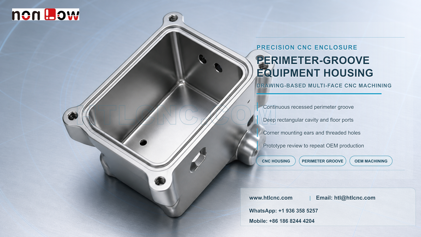
Perimeter-groove equipment housing custom CNC machining coordinates a recessed rim channel, deep cavity, corner mounting ears, internal holes and side interfaces for prototype and repeat OEM production.
Perimeter-groove equipment housing custom CNC machining is used when a compact enclosure must combine a deep rectangular cavity with a continuous recessed channel around the open rim, corner mounting ears and interfaces on the floor and side walls. The pictured housing visibly includes a machined perimeter groove, four corner ears with holes, a deep cavity with internal fillets, holes entering the cavity and an exterior side boss or port. HTL CNC provides custom CNC machining, precision CNC parts, deep-cavity milling, multi-face CNC machining, prototype validation, low-volume production and repeat drawing-based manufacturing for overseas OEMs and equipment builders. The image does not establish material grade, tolerances, groove function, sealing performance, finish or final application; those requirements must be defined by the customer's released drawings, STEP file and assembly information.
What Is a Perimeter-Groove Equipment Housing?
A perimeter-groove equipment housing is a machined enclosure with a continuous recessed channel following the open rim. That channel may accommodate a gasket, seal, adhesive, wire or another assembly feature, but its actual purpose cannot be confirmed from appearance. The housing also provides an internal volume and external mounting points in one integrated body.
For engineering review, the buyer should identify the groove's functional cross-section, the mating cover geometry, the primary seating land and the surfaces that locate the housing in the final assembly. This information determines which dimensions and relationships must be prioritized during machining and inspection.
Why Groove Continuity Matters More Than Width Alone
A complete groove specification should define width, depth, corner radius, path, start and end condition when applicable, and its relationship to the surrounding rim. If the channel supports a sealing function, the drawing may also need to identify surface condition, allowable interruptions, groove volume and finish allowance. No leakage or environmental rating should be assumed from the photograph.
The groove follows rounded corners and passes near mounting ears, so cutter diameter, interpolation path and tool deflection must be considered. Inspection may use calibrated depth and width tools, optical measurement, CMM scanning or a dedicated profile method according to the released tolerance and access.
Rim Flatness and Corner Mounting-Ear Relationships
The open rim forms a broad seating region around the cavity. Four projecting ears introduce holes at the corners, while the groove remains close to the edge. The drawing should state whether the rim is a controlled mounting face, how each corner hole is classified and whether hole position relates to the cavity, groove centerline or an exterior datum.
Workholding must support the housing without distorting the rim or damaging the channel. A practical process may establish stable exterior reference surfaces, rough the cavity, then finish the rim, groove and related hole pattern after the body is stable. The exact route depends on stock form, material, wall thickness, tolerance and quantity.
Deep Cavity, Internal Fillets and Floor Holes
The cavity contains smooth wall-to-floor transitions and several visible internal holes. Tool reach, chip evacuation and remaining wall rigidity influence the roughing and finishing plan. Internal corner radii should match functional needs while remaining accessible to a rigid cutter.
If a floor or wall hole intersects another passage, the supplier should plan both-side edge control and cleanliness verification. Loose burrs or retained chips can interfere with assembly even when the main dimensional inspection is acceptable.
Side Interfaces and Multi-Face CNC Machining
The exterior side wall includes a machined opening and a projecting boss or port. These features approach the cutter from directions different from the cavity and corner holes. A qualified 3-axis route with controlled refixturing may be appropriate, while indexed 4-axis or 5-axis CNC machining can be evaluated when setup reduction improves access or feature relationships.
Axis count is not a quality claim by itself. Supplier review should identify where datum transfers occur, which features share a setup and how the side interface is measured relative to the rim and cavity.
How Should Finishing and Assembly Validation Be Specified?
The metallic appearance does not confirm an as-machined condition or any particular treatment. Customers may specify anodizing, plating, passivation, blasting, polishing, painting or another process compatible with the confirmed material. The finish requirement should identify the groove, rim, threads, internal surfaces and masked zones, plus any dimensional allowance caused by coating thickness.
Prototype validation should use the intended mating cover or adjacent component where possible. Engineering teams can check rim contact, groove alignment, corner-hole registration, internal clearance and side-interface access. Leakage, pressure or environmental testing should be performed only when the customer specifies the method and acceptance criteria.
Inspection Evidence for OEM Supplier Qualification
A risk-based inspection plan may cover groove width and depth, rim condition, cavity dimensions, wall thickness, internal-hole position, corner-ear pattern, side-interface location, threads and drawing-defined geometric controls. First-article data and production-lot records should reference the part number, drawing revision, purchase order and production lot.
Overseas procurement teams can define material documents, finishing records, sampling frequency, traceability and record retention during quotation. HTL's custom CNC machining service supports engineering and quality review before production controls are released.
Prototype to Repeat OEM Production
After prototype approval, qualified fixtures, controlled programs, first-piece checks, tool-life monitoring and formal revision management support repeat-order consistency. The perimeter groove and rim should remain protected during handling, finishing and export packaging so their edges are not dented or contaminated.
HTL's prototype and low-volume CNC machining service provides a staged route from engineering samples to pilot quantities and recurring supply. Buyers should align annual demand, order cadence, destination, packaging and delivery planning before ramp-up.
RFQ Package for Perimeter-Groove Housing Manufacturing
Send the released 2D drawing and STEP file with material, prototype and production quantities, annual demand, groove cross-section and function, rim and mounting datums, hole and side-interface definitions, tolerances, surface finish, inspection-document scope, validation requirements, packaging and target delivery. Include the mating cover or assembly data when it affects the groove, rim or hole pattern. HTL CNC can then prepare a manufacturing, quality and supply plan for the actual perimeter-groove equipment housing custom CNC machining project.
Website: www.htlcnc.com Email: htl@htlcnc.com WhatsApp: +1 936 358 5257 Mobile: +86 186 8244 4204
Have a part ready for engineering review?
Send your drawing, STEP file, material and quantity directly to HTL CNC for a manufacturing quotation.