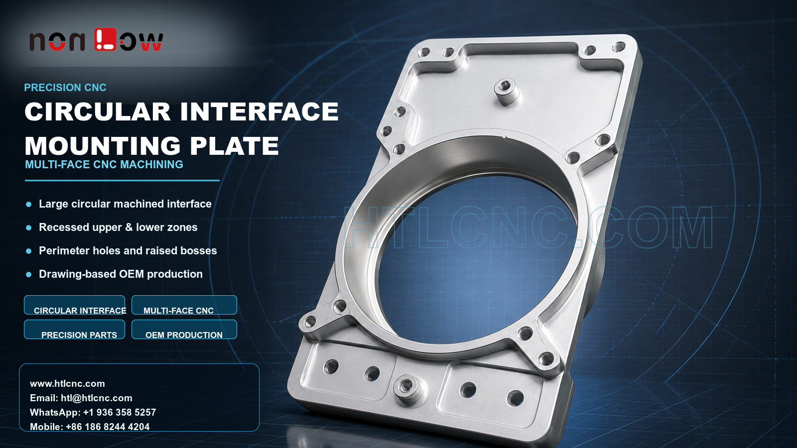
Precision CNC circular interface mounting plate machining coordinates a large machined bore, raised annular wall, recessed mounting zones, perimeter holes and bosses for drawing-based OEM production.
Precision CNC circular interface mounting plate machining combines a large central opening with multiple surrounding features that must remain related to one controlled datum system. The pictured component visibly includes a large machined circular interface, a raised annular wall, upper and lower recessed zones, perimeter holes, local corner supports and two raised bosses. HTL CNC supports overseas OEMs, equipment builders, engineering teams and procurement organizations with custom CNC machining, precision CNC parts, multi-face CNC milling, prototype validation, low-volume production and repeat drawing-based OEM manufacturing. The image does not confirm material grade, tolerance, fit or final application; those requirements must be defined by the customer's released 2D drawing, STEP model and assembly information.
What Is a Precision CNC Circular Interface Mounting Plate?
This part category provides one broad body around a dominant circular interface while also carrying several mounting and locating zones. Its engineering value depends on how the large opening, surrounding face, perimeter holes, recessed pockets and bosses work together in the final assembly. The visible shape alone cannot establish whether the circular region receives a bearing, cover, motor, optical item or another component.
For sourcing purposes, the buyer should identify the functional seating face and axis first. Related features can then be evaluated against that datum structure instead of being treated as disconnected dimensions. This gives the supplier a clearer basis for process planning, workholding and inspection.
Large-Bore Machining and Annular Wall Control
The dominant circular opening contains a broad machined bore and a raised annular wall. A released drawing may need to define diameter, depth, shoulder width, seating-face flatness, surface condition and geometric relationships to the base. No fit or tolerance should be inferred from the photograph.
Possible operations include circular interpolation, boring, reaming and face milling according to size, access and requirements. Roughing can leave controlled finishing stock around the bore and annular surface until the plate is stable. Inspection may use bore gauges, internal micrometers, depth tools, roundness equipment or CMM probing where appropriate.
Upper and Lower Recessed Mounting Zones
Recessed regions above and below the circular interface create multiple floor levels and local shoulders. These features may provide clearance or component seating, but their function must be confirmed from the assembly. The RFQ should identify which floor is a datum, which pockets are clearance-only and whether the upper and lower zones must remain parallel or positioned relative to the main bore axis.
Pocket milling strategy must consider tool access near the annular wall, corner radii, wall thickness and remaining stiffness. If the drawing requires small internal radii, the buyer and supplier should review whether they are functionally necessary or can be adjusted for a more stable cutter and shorter cycle.
Perimeter Holes, Corner Supports and Raised Bosses
The plate contains several holes around its outer boundary and two visible raised bosses near the top and bottom regions. The drawing should distinguish threaded, clearance, locating and inspection holes. Diameter alone is not enough when a hole pattern must align with the large circular interface or a mating assembly.
Raised bosses may require controlled height, diameter, thread condition or location. Their exact function is unknown, so the inspection plan should follow the released callouts. Pin gauges, thread gauges, height measurement, optical systems or CMM inspection can be used according to access and tolerance.
Workholding for a Large Opening and Thin Remaining Sections
Removing a large central area changes how the plate carries clamping force. Workholding should support broad datum regions without distorting the annular wall, corner supports or recessed floors. A practical sequence may establish stable base surfaces first, rough the opening and pockets, then finish the bore, seating faces and related hole pattern after movement has been controlled.
The correct setup plan depends on stock form, material, part size, quantity and tolerance. HTL's custom CNC machining service reviews those inputs before defining fixture contact points, operation order and in-process verification.
Choosing 3-Axis, Indexed 4-Axis or 5-Axis Access
The broad faces may be machined on a 3-axis CNC with qualified refixturing. Indexed 4-axis or 5-axis CNC machining can be evaluated when side holes, angled access or setup reduction improve control of cross-face relationships. Axis count is not a substitute for a stable datum plan or inspection evidence.
For supplier qualification, procurement teams should ask which features share a setup, where datum transfers occur and how the large bore is verified relative to the mounting zones. A credible answer should connect machine access, workholding and measurement rather than simply naming equipment.
First-Article Evidence for OEM Supplier Approval
A risk-based first-article plan may include the large bore, annular seating face, pocket depths, boss heights, perimeter-hole positions, base flatness and drawing-defined geometric controls. Overseas OEMs can request selected dimensional data, a first-article inspection report or production-lot records for agreed critical characteristics.
Report format, sampling frequency, traceability and document retention should be agreed before quotation. Inspection records must reference the correct part number, drawing revision and production lot. Drawing confidentiality and controlled access to customer STEP files can also be included during supplier onboarding.
Prototype Assembly Review Before Repeat Production
Prototype validation should use the intended mating components whenever possible. Engineering teams can check seating around the circular interface, hole-pattern alignment, boss engagement, pocket clearance, fastener access and surface-treatment allowance. Any change should be released through an updated 2D drawing and STEP revision before production ramp-up.
After approval, controlled programs, qualified fixtures, first-piece checks, tool-life management and formal version control support repeat-order consistency. HTL's prototype and low-volume CNC machining service provides a staged path from engineering samples to low-volume ramp-up and recurring OEM supply.
Finish Definition and Export Packaging
The metallic appearance does not establish material or final finish. A customer may specify an as-machined condition, anodizing, plating, passivation, blasting, brushing, polishing, painting or another process compatible with the confirmed material. The finish specification should identify masked bores, protected seating faces, coating allowance, threaded regions and cosmetic zones.
The large circular edge, corner supports and raised bosses require protection during handling and export. Separators, edge protection, individual wrapping or formed trays can reduce impact and metal-to-metal contact. Labels should connect part number, revision, quantity and lot to the supplied quality documents.
RFQ Checklist for Drawing-Based Custom Manufacturing
Send the released 2D drawing and STEP file with material requirements, prototype and production quantities, annual demand, circular-interface function, critical datums, hole and boss definitions, tolerance requirements, surface finish, inspection-document scope, packaging expectations, destination and requested delivery date. Include mating-part information when the large opening or mounting pattern must align with another assembly. HTL CNC can then prepare a process, inspection and delivery plan based on controlled engineering requirements.
Website: www.htlcnc.com Email: htl@htlcnc.com WhatsApp: +1 936 358 5257 Mobile: +86 186 8244 4204
Have a part ready for engineering review?
Send your drawing, STEP file, material and quantity directly to HTL CNC for a manufacturing quotation.