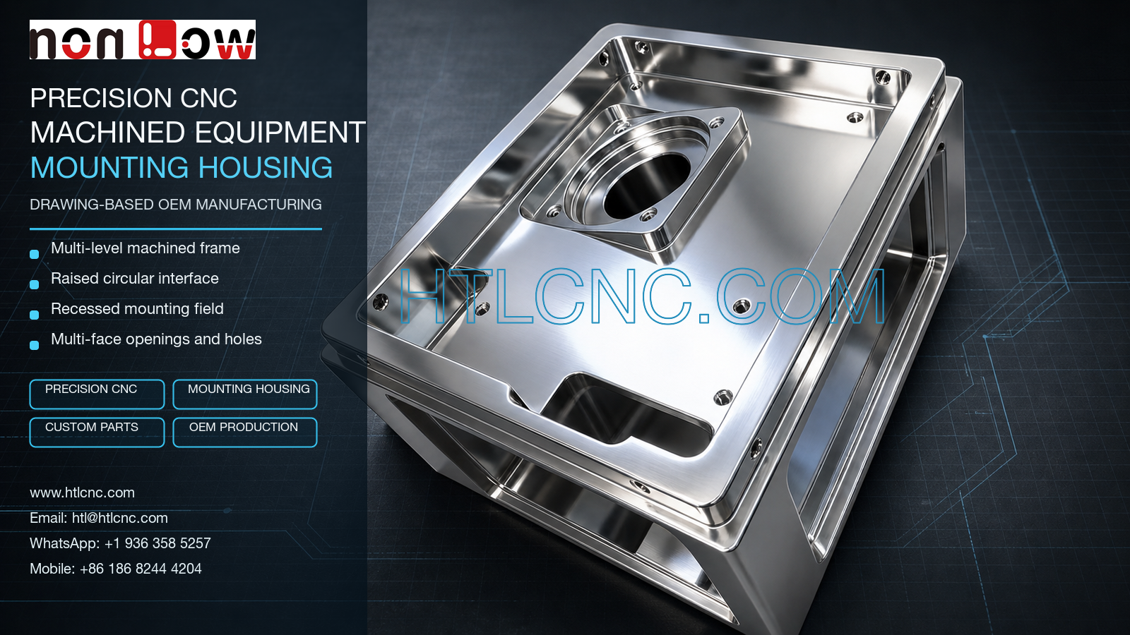
A precision CNC equipment mounting housing can integrate a raised circular interface, recessed mounting field, multi-level frame and cross-face openings in one machined body.
A precision CNC equipment mounting housing combines structural support, component location and multiple assembly interfaces in one machined body. The pictured part has a broad recessed mounting field, a raised circular interface with a central bore, perimeter steps, countersunk holes, a deep end opening and large windows through the side frame. These visible features make datum control, multi-level face machining and cross-face inspection central to the manufacturing plan. HTL CNC provides drawing-based custom CNC machining for equipment builders, product-development companies, automation OEMs, contract manufacturers, engineers and procurement teams that need precision CNC parts from prototypes through repeat production. Material, tolerances, surface finish and final use must be confirmed from the customer's released 2D drawing and STEP model rather than inferred from the image.
What Does the Housing Integrate?
This component appears to consolidate several functions that might otherwise require separate plates, brackets or spacers. The outer frame can provide structural support, the recessed field can locate an internal assembly, and the raised circular region can establish a controlled interface for a shaft, lens, connector, bearing, seal or another mating component. Its exact function cannot be established from appearance, but the geometry clearly shows why related features must be manufactured and inspected as one system.
For supplier qualification, a buyer should identify which face establishes the primary datum, which circular or rectangular feature locates the mating assembly, and which holes are clearance, fastening or alignment features. A drawing that distinguishes functional interfaces from cosmetic surfaces allows the machining supplier to concentrate process control and inspection evidence where it affects assembly.
Multi-Level Face and Recessed-Field Machining
The housing does not have one simple flat surface. It includes perimeter rails, recessed floors, stepped transitions and an elevated circular boss. A practical process plan normally preserves stable reference surfaces while rough material is removed, then finishes the critical levels in a controlled sequence. This reduces the risk that later clamping or stock removal changes a previously completed relationship.
Pocket depth, rail height, floor flatness and the location of the raised interface may affect how another part seats in the housing. The RFQ should therefore state which levels are functional, whether a gasket or cover contacts the perimeter, and whether tool marks in the recessed field are acceptable. Internal corner radii should match realistic cutter access unless a special relief or secondary process is specified.
Raised Circular Interface and Bore Control
The most prominent local feature is a raised circular interface set on an angled or multi-sided boss. Its visible concentric steps, central bore and surrounding fastener holes require a shared datum strategy. Depending on the released geometry, the route may use circular interpolation, boring, drilling, countersinking, thread machining or other operations. The machine-axis choice must be based on tool access, tolerance, fixture stiffness and batch quantity, not on a generic claim that more axes automatically produce better parts.
Engineering review should define bore diameter, depth, concentric steps, face position, hole pattern, thread callouts where applicable and the relationship to the primary mounting field. If the interface receives a bearing, seal, optical element or locating sleeve, the mating requirement and finish allowance should be stated explicitly. A supplied mating sample can be useful during prototype validation when drawing information alone does not capture the complete assembly condition.
Cross-Face Openings and Setup Strategy
Large windows and smaller holes are visible on faces that are not parallel to the main recessed field. These features create access and datum-transfer decisions. A controlled 3-axis CNC machining route with qualified refixturing may be efficient for some versions, while indexed 4-axis or 5-axis CNC machining can be evaluated when fewer setups improve access to side openings or preserve important positional relationships.
Fixture design must support the housing without covering required cutter paths or marking finished surfaces. Locating points should be repeatable and robust enough for the expected quantity. For low-volume production, flexible workholding may reduce preparation time; for repeat OEM supply, dedicated soft jaws or fixtures may improve loading consistency and reduce the risk of operator-dependent variation.
Managing Rigidity in an Open-Frame Part
The part includes large openings and a relatively broad machined field. As material is removed, remaining walls and rails may respond differently to clamping force and heat. A staged roughing and finishing route can retain support until the geometry is stable enough for final passes. Tool reach, chip evacuation and cutting direction should be reviewed around the deep end opening and undercut-looking transitions.
The final drawing should state permitted edge breaks and controlled sharp edges. Deburring must remove burrs from openings and countersinks without rounding locating edges, enlarging holes or damaging the entry of a thread. If appearance matters, cosmetic zones should be identified separately from hidden structural areas so the supplier can plan handling and inspection accordingly.
What Should Be Included in the Inspection Plan?
Inspection should follow the assembly function of the housing. Relevant characteristics may include primary-face flatness, perimeter height, recessed-field depth, circular-bore size and position, boss-face location, hole-pattern position, countersink geometry, side-window size, cross-face relationships and drawing-defined geometric controls. The appropriate tools may include calipers, micrometers, depth gauges, bore gauges, pin or thread gauges, height measurement, optical systems and CMM inspection according to tolerance and access.
For prototype validation, overseas OEMs can request selected dimensional results, a first-article inspection report or evidence tied to critical features. Repeat orders may use defined in-process checks and lot-level records. Inspection scope, document format, traceability and retention period should be agreed before quotation so both supplier and buyer understand what evidence is included.
Surface Finish and Interface Protection
The housing can be supplied as machined or with a customer-specified treatment compatible with the released material. Anodizing, plating, passivation, blasting, brushing, polishing, painting or another finish should only be selected after material and functional requirements are confirmed. Coating allowance, masked faces, plugged holes, thread protection, color range and cosmetic acceptance should be documented before production.
Raised circular faces, sealing rails and machined edges are vulnerable to contact damage during transfer and export shipping. Protective caps, separators, individual wrapping or formed trays can prevent metal-to-metal contact. Packaging labels should preserve part number, drawing revision, quantity and lot identity to support receiving inspection and repeat-order traceability.
Prototype Review Before Repeat OEM Production
A prototype should be evaluated as an assembly component, not only as an isolated metal part. Buyers can check seating on the primary face, alignment of the circular interface, fastener access, side-window clearance, mating-part fit, finish appearance and packaging protection. Any design or tolerance change should be released under a new revision before low-volume ramp-up.
After approval, controlled programs, documented workholding, defined inspection points and formal change management support repeat production. Expected batch size, annual demand, delivery schedule and destination help HTL CNC review machining capacity, fixture investment, finishing lots, inspection workload and export planning. Drawing confidentiality and access to controlled files can also be addressed during supplier onboarding.
RFQ Information for a Manufacturing Review
Send the released 2D drawing and STEP file together with the specified material, prototype and production quantities, annual demand, critical tolerances, thread and bore requirements, surface finish, inspection-document needs, packaging expectations, delivery schedule and destination. If only a sample is available, include clear assembly context and identify which interfaces must be duplicated. HTL CNC can then review the actual precision CNC equipment mounting housing and prepare a process and quality plan based on controlled requirements.
Website: www.htlcnc.com Email: htl@htlcnc.com WhatsApp: +1 936 358 5257 Mobile: +86 186 8244 4204
Have a part ready for engineering review?
Send your drawing, STEP file, material and quantity directly to HTL CNC for a manufacturing quotation.