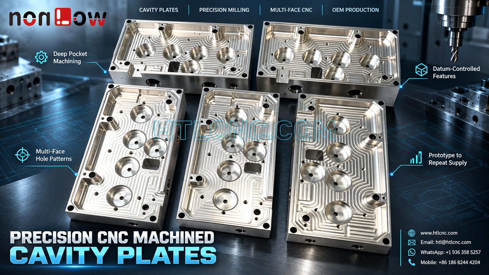
Precision CNC machined cavity plates require coordinated deep-pocket milling, datum-controlled bosses, hole patterns and inspection evidence for prototype and repeat OEM supply.
Precision CNC machined cavity plates combine broad recessed regions, repeated internal bosses, stepped floor geometry, perimeter walls, corner holes, side ports and local square pockets in one component. The photograph shows five related rectangular plates with similar feature families, which makes process consistency and revision control central sourcing questions. The image does not establish the metal grade, tolerance class, surface treatment, final application or whether every plate shares one drawing. Those details must come from the buyer's controlled 2D drawings, STEP models and specifications. HTL CNC supports overseas OEMs, equipment builders, product-development companies, contract manufacturers, engineers and procurement teams with drawing-based custom CNC machining, prototype validation, low-volume production and repeat supply.
What Makes a Cavity Plate Difficult to Source?
A cavity plate is not defined only by its outside length and width. Assembly or process performance may depend on the relationship among the recessed floor, internal bosses, perimeter walls, locating holes and features machined from the side faces. If those features are planned as unrelated dimensions, each can pass inspection while the completed part still fails to align with its mating components.
Supplier review should therefore begin with functional datums and feature relationships. The RFQ should identify the primary seating face, the locating holes or edges, any critical boss diameters and heights, and the side features that must align with the main cavity. A mating-component model can help the manufacturing team review access and inspection without guessing the plate's end use.
Deep-Pocket CNC Milling and Tool-Reach Planning
The visible recessed regions contain broad floors and multiple depth levels. Deep-pocket CNC milling requires a practical balance among cutter reach, tool rigidity, corner radius, chip evacuation and surface access. A long tool may reach the floor but can increase deflection and vibration; a larger cutter is more rigid but may not enter narrow transitions.
A process plan may remove bulk material with a stable roughing tool, leave controlled stock, then finish walls, floors, bosses and local pockets in a datum-linked sequence. Exact tooling and cutting conditions depend on the specified material, geometry, tolerance, quantity and machine configuration. Internal corners should carry achievable radii unless the released drawing explicitly calls for another manufacturing method.
Protecting Bosses and Thin Sections During Material Removal
Multiple raised circular bosses remain inside each cavity. Their diameter, height and position may be functionally important, but the photograph does not confirm their purpose. Removing surrounding material can leave these features less supported, so roughing sequence and finishing allowance should avoid excessive local load.
Thin perimeter walls and narrow lands can also respond to clamping force and heat. Stable workholding should support a reliable datum surface without obstructing the side ports or crushing finished walls. Where the geometry warrants it, intermediate inspection can confirm that stock remains available before the final finishing pass.
Coordinating Main Cavities with Side Ports and Hole Patterns
The plates visibly include holes and openings on both top and side faces. Multi-face machining should preserve the relationship between these features and the primary cavity. The suitable route may use controlled refixturing, indexed 4-axis positioning or 5-axis CNC machining, depending on access, feature direction, rigidity, tolerance and production quantity.
Machine-axis count alone does not guarantee alignment. A qualified setup must define how the datum is transferred, how the part is located after turning or indexing, and how side holes are verified relative to the recessed geometry. HTL's custom CNC machining service supports drawing-led process selection rather than forcing every part into the same route.
Toolpath Marks, Finish Requirements and Edge Control
Parallel toolpath marks are visible across the cavity floors. Their presence does not establish the required roughness or whether another finishing operation is specified. The buyer should define drawing-based roughness values only where function requires them and identify cosmetic zones separately from sealing, seating or locating surfaces.
Deburring should remove loose edges without rounding a datum shoulder, enlarging a small hole or changing a square-pocket corner beyond the approved geometry. If a surface treatment is required, the RFQ should state the exact process, masking areas, coating allowance, cosmetic acceptance criteria and whether dimensions apply before or after treatment.
Inspection Evidence for Related Plate Variants
For a family of cavity plates, the inspection plan should cover both common geometry and version-specific differences. Risk-based checks may include overall size, cavity depth, boss diameter and height, floor-to-datum relationship, hole position, side-port alignment, wall thickness, flatness or profile only where the drawing requires them.
Measurement can combine calibrated hand tools, depth and height systems, pin or thread gauges, optical equipment and CMM inspection according to access and tolerance. Every report should identify the exact part number, drawing revision, material lot and production lot. Results from one related plate must not be reused as evidence for another configuration.
Prototype Qualification Before Repeat OEM Production
Prototype quantities allow the engineering team to verify fit, seating, hole alignment, fastener access, cavity clearance and the proposed inspection method. If testing changes a boss, pocket, hole or datum, the 2D drawing and STEP model should be released together so manufacturing and quality records remain synchronized.
After sample approval, controlled CNC programs, qualified fixtures, approved material and finishing sources, first-piece checks and revision control support low-volume ramp-up and repeat orders. HTL's prototype and low-volume CNC machining service supports staged qualification before recurring supply.
Supplier Qualification, Confidentiality and Capacity Planning
Overseas buyers should confirm how a supplier controls customer drawings, model access, program revisions and obsolete files. A capable review also considers machining capacity, inspection availability, outside-process coordination and corrective-action records. Where designs are confidential, include the required NDA and file-transfer process before releasing complete models.
Annual demand, batch size, release frequency, destination and target delivery schedule help the supplier plan stock, machining time, inspection workload and export packaging. Broad machined faces should be separated during shipment so one plate cannot scratch or impact another. Labels should retain part number, revision, quantity and lot identity.
RFQ Checklist for Precision CNC Machined Cavity Plates
Send the released 2D drawing and STEP file for each plate, part number and revision, exact material specification, prototype and production quantities, annual demand, functional datums, critical cavity and boss features, hole and side-port requirements, tolerances, surface-finish requirements, inspection-document scope, packaging, destination and delivery schedule. Include mating models when alignment or clearance is critical. HTL CNC can then review the precision CNC machined cavity plate project and propose a controlled deep-pocket milling, inspection and repeat-supply plan.
Website: www.htlcnc.com Email: htl@htlcnc.com WhatsApp: +1 936 358 5257 Mobile: +86 186 8244 4204
Have a part ready for engineering review?
Send your drawing, STEP file, material and quantity directly to HTL CNC for a manufacturing quotation.