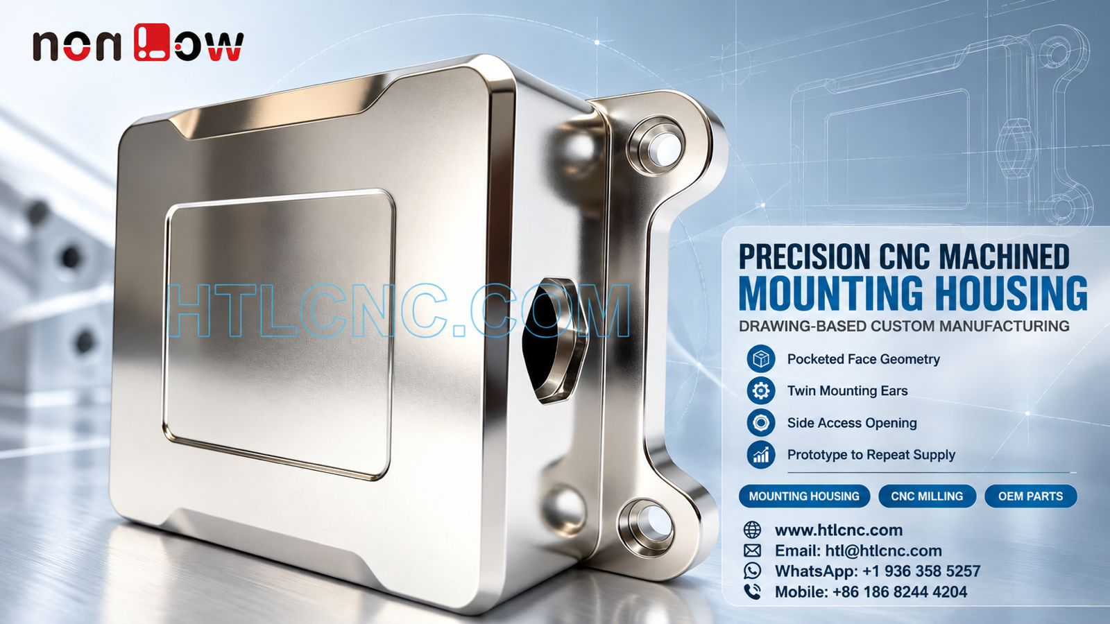
A precision CNC machined mounting housing combines a broad pocketed face, twin mounting ears, side access opening and multi-face datum control for prototype and repeat OEM supply.
A precision CNC machined mounting housing can combine enclosure-like surfaces and bracket-style interfaces in one compact part. The pictured component visibly includes a broad rectangular body, a large recessed face, a shaped upper notch, two projecting mounting ears with circular holes and a side access opening. The photograph does not establish its material grade, surface-treatment process, tolerances, load rating, sealing function or final application. Those requirements must come from the buyer's released 2D drawing, STEP model and technical specification. HTL CNC supports overseas OEMs, product-development companies, equipment builders, engineers and procurement teams with drawing-based custom CNC machining, prototype validation, low-volume production and repeat supply.
What Makes This Mounting Housing a Multi-Feature Part?
The component is not simply a flat cover or a two-hole bracket. Its front pocket, outer body, projecting ears and side opening occupy different planes and may serve different assembly relationships. A supplier must understand which surface seats against the mating structure, which holes locate the part, which features provide clearance and which faces are cosmetic.
An RFQ should include the assembly orientation and mating models when available. That information lets the engineering team review fastener access, tool clearance, edge conditions and possible interference without guessing the product's end use. HTL's custom CNC machining service uses this drawing-led review to select the process route.
Twin Mounting Ears Need One Datum Strategy
Two mounting ears are visible on the rear side of the part, each with a circular hole and a surrounding recessed feature. The drawing should define hole type, size, depth and position, then identify whether one or both holes provide location. Individual hole diameters can pass inspection while the pair still fails assembly if their spacing, orientation or relationship to the seating face is wrong.
A stable datum strategy normally links the ear holes to the functional mounting face and the main body. The exact datums and geometric controls must follow the released drawing. If the ears are thin relative to the body, workholding and cutting order should also avoid local distortion or marking of finished surfaces.
Pocketed Face Geometry and Controlled Floor Depth
The broad front surface contains a large shallow pocket with rounded corners. The OEM should specify pocket length, width, depth, corner radii, floor condition and the relationship to the outer profile. If the pocket supports a label, insert, mating plate or another customer-defined feature, the functional zone and cosmetic criteria should be separated clearly.
Practical cutter radii and open tool access can support stable milling, but floor flatness and wall consistency still depend on stock condition, clamping and finishing sequence. A theoretical sharp internal corner should not be assumed achievable by ordinary end milling unless the drawing defines another method or an approved relief.
Side Access Opening and Cross-Feature Alignment
A shaped opening is visible on the side wall. Its function cannot be confirmed from the photograph, so the drawing should state its profile, size, depth, edge break and positional relationship to the pocket, ear holes and mounting face. When a side opening intersects an internal volume, inspection and deburring must address the inner edge as well as the visible entry.
Depending on access, tolerance, quantity and part size, the process may use controlled refixturing, indexed 4-axis positioning or 5-axis CNC machining. Axis count is not a substitute for datum transfer. The process plan should explain how the side feature remains connected to the coordinate system established for the main body.
Machining Sequence for the Body, Pocket and Ears
A suitable route may establish broad reference faces first, rough the main body and pocket while support remains, then finish the ear interfaces and side opening from qualified references. The actual sequence depends on the specified material, stock form, tolerance and production quantity. No process should be selected from the metallic color alone.
Balanced stock removal can help preserve the relationship between the pocketed face and mounting features. Critical surfaces should be protected during later setups, and fixtures should clamp rigid regions without blocking inspection points or leaving unacceptable marks.
Inspection Evidence for OEM Supplier Qualification
A risk-based plan may cover overall envelope, pocket size and depth, outer profile, ear-hole diameter and spacing, recessed-hole geometry, side-opening profile, face relationships and drawing-defined flatness, position or profile controls. Measurement may combine calibrated hand tools, depth and height systems, pin gauges, optical equipment and CMM inspection according to feature access and tolerance.
The inspection setup should reproduce the drawing datum scheme. Measuring ear-hole spacing from a convenient nonfunctional edge can create data that does not represent assembly performance. First-article records should identify part number, revision, production lot, material lot when required and the equipment used for each reported result.
Finish Requirements Must Be Released, Not Inferred
The warm metallic appearance in the image does not identify an alloy, plating, polishing, anodizing or any other treatment. The RFQ should provide the exact material and finish standards, approved appearance reference, texture or gloss range, masking zones, dimensional allowance and certification scope. HTL will not infer a process from color.
Ear holes, seating faces and the side opening may require masking or post-finish verification when buildup could affect assembly. The drawing should state whether dimensions apply before or after treatment and which surfaces are functional, cosmetic or noncritical.
Prototype Validation Before Repeat Production
Prototype quantities allow the OEM team to check mounting-hole alignment, seating, side-opening access, pocket clearance, fastener installation and surface appearance with real mating parts. If the review changes the pocket, hole pattern, profile or finish, the 2D drawing and STEP model should be updated together under a new revision.
After approval, controlled programs, qualified fixtures, first-piece checks, revision management and lot-linked inspection records support low-volume ramp-up and recurring orders. HTL's prototype and low-volume CNC machining service provides a staged route from engineering samples to repeat OEM production.
Packaging, Revision Control and Delivery Planning
The projecting ears and finished broad faces should be protected from impact and metal-to-metal contact. Packaging may use sleeves, separators, protective film or formed trays selected from the actual geometry and finish. Labels should show part number, revision, quantity and production lot.
Annual demand, release frequency, destination and target schedule help the supplier plan material, machine capacity, finishing, inspection and export packing. Procurement teams should also define how obsolete revisions are quarantined so an earlier ear-hole or side-opening configuration cannot enter a current shipment.
RFQ Checklist for a Precision CNC Machined Mounting Housing
Send the released 2D drawing and STEP file, assembly orientation or mating model, exact material specification, prototype and production quantities, annual demand, functional datums, pocket requirements, ear-hole and recess definitions, side-opening geometry, tolerances, edge requirements, finish specification, cosmetic and masking zones, inspection-document scope, packaging, destination and delivery schedule. HTL CNC can then review the precision CNC machined mounting housing and propose a controlled machining, inspection and repeat-supply plan.
Website: www.htlcnc.com Email: htl@htlcnc.com WhatsApp: +1 936 358 5257 Mobile: +86 186 8244 4204
Have a part ready for engineering review?
Send your drawing, STEP file, material and quantity directly to HTL CNC for a manufacturing quotation.