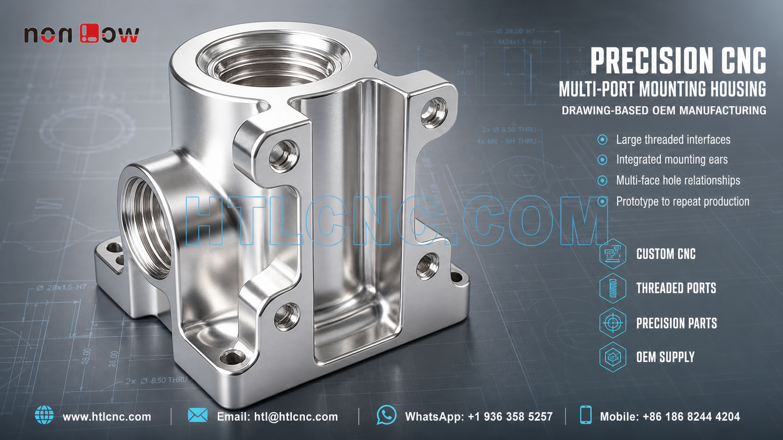
B2B custom CNC machining for compact multi-port mounting housings with large threaded interfaces, integrated ears, recessed support geometry and cross-face hole relationships.
A precision CNC multi-port mounting housing can combine fluid, optical, mechanical or equipment interfaces in one compact body, but the visible geometry alone does not establish its final application. The pictured component contains a large threaded bore on the top, a second large threaded side port, several smaller holes on integrated mounting ears, vertical ribs and a recessed central region. These features make multi-face datum transfer, thread inspection and repeatable workholding important for OEM precision parts. Material, thread standards, tolerances, finish and use must follow the customer's released drawing and STEP model.
HTL CNC provides drawing-based custom CNC machining for overseas equipment builders, product-development teams, contract manufacturers, engineers and procurement organizations. We support prototype validation, low-volume production and repeat supply while keeping quotations, programs and inspection records linked to the controlled revision.
Start Supplier Qualification with Interface Definitions
A complete RFQ should identify the function of each large port, the locating faces, the mounting-hole pattern and the surfaces that mate with adjacent components. Buyers should provide the released 2D drawing, STEP file, specified material, thread details, prototype and production quantities, critical tolerances, surface-finish requirements, inspection-document scope, packaging expectations and delivery destination.
Thread callouts should state form, pitch, class or fit where applicable, effective depth, entry chamfer and any gauge requirement. If a port must align with an internal passage or mating component, that relationship should be included in the datum scheme and first-article plan rather than left as a general note.
Large Threaded Port Machining
The top and side interfaces are large relative to the housing body. Depending on the released specification, the route may include drilling, circular interpolation, boring, threading with a dedicated tool or thread milling. Tool selection must reflect the actual material, thread definition, depth, relief and access.
Thread milling may support controlled entry and adjustment in some applications, while another method may be more efficient for a different geometry or quantity. The supplier should not select a route from appearance alone. Port diameter, thread condition, face relationship and cleanliness should be verified with agreed gauges and measurement methods.
Cross-Face Relationships and Multi-Axis Process Selection
One major port is vertical and another is horizontal. Smaller holes are distributed across mounting ears and side faces. This architecture requires a reliable transfer between machining orientations. A controlled 3-axis route with qualified refixturing may be appropriate, while indexed 4-axis or 5-axis CNC machining can reduce setups when access and positional relationships justify it.
More axes are not automatically better. The selected process should balance fixture stiffness, datum continuity, tool reach, collision clearance, cycle time and inspection access. Features that must align across faces should be programmed and inspected from common references wherever practical.
Integrated Ears, Ribs and Recessed Support Geometry
The housing includes mounting ears at several heights, vertical ribs and a recessed central opening. These features affect cutter access and local rigidity as material is removed. Roughing and finishing order should retain support around slender ears and tall walls until important bores, threads and mounting surfaces are established.
Internal radii, rib transitions and recessed floors should be defined on the drawing. Deburring must remove sharp material without changing a locating edge, damaging a thread entry or rounding a controlled corner. Where the housing includes cosmetic faces, functional datums and appearance zones should be identified separately.
Inspection Evidence for OEM Approval
An agreed inspection plan may cover the primary mounting face, large port diameters, thread form and depth, port-to-port orientation, smaller hole positions, ear thickness, rib and recess geometry, edge condition and drawing-defined geometric controls. Thread gauges, bore measurement, height equipment, optical systems and CMM inspection may be selected according to the tolerance and access.
For supplier onboarding, buyers should define whether prototypes require selected dimensional results or a first-article report and whether recurring orders require lot-level records. Material and finishing documents should be supplied only within the agreed scope and traceable to the relevant batch.
Finish, Cleanliness and Protected Packaging
The part can be delivered as machined or with a customer-specified treatment compatible with the released material. Anodizing, plating, passivation, blasting, brushing, polishing, painting or another finish should be quoted only when specified. Masked faces, thread protection, coating allowance, color and cosmetic criteria should be reviewed before production.
Threaded ports and machined sealing or mounting faces may require protection during cleaning, storage and export transport. Caps, sleeves, separation trays or other packaging can reduce contamination and metal-to-metal contact. Packaging labels should preserve part number, revision and lot identity.
Prototype Review to Repeat OEM Supply
Prototype approval should verify interface engagement, port alignment, mounting fit, accessible fasteners, edge condition and surface expectations. Procurement teams can also review confidentiality, engineering response, revision control, inspection evidence, packaging and delivery performance before approving repeat orders.
After sample acceptance, documented workholding, controlled programs, defined inspection points and formal change management support low-volume ramp-up and recurring production. Annual demand and delivery forecasts help plan material, capacity, fixtures, finishing batches and shipment schedules.
Send a Complete RFQ
For engineering review, send the released 2D drawing and STEP file with the specified material, thread callouts, quantity, critical tolerances, surface finish, inspection requirements, packaging needs, annual demand and delivery destination. HTL CNC can then evaluate a realistic process for the actual multi-port mounting housing rather than estimate from a photograph.
Website: www.htlcnc.com Email: htl@htlcnc.com WhatsApp: +1 936 358 5257 Mobile: +86 186 8244 4204
Have a part ready for engineering review?
Send your drawing, STEP file, material and quantity directly to HTL CNC for a manufacturing quotation.