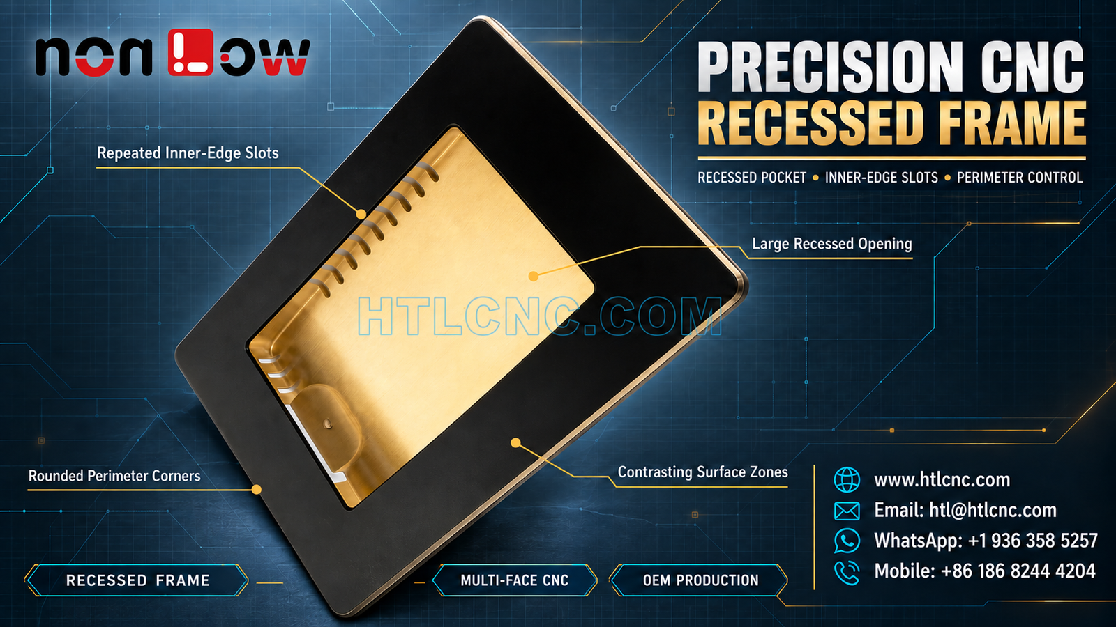
A precision CNC recessed frame combines a large rounded opening, repeated inner-edge slots, broad perimeter faces and contrasting surface zones that require coordinated machining, finishing and inspection.
A precision CNC recessed frame can appear visually simple while concentrating several manufacturing risks around one large opening. The pictured part visibly has a broad rectangular perimeter, rounded outer and inner corners, a deep recessed central area, repeated narrow slots along an inner edge, local cutouts and a small circular recessed feature. Its black and gold-colored surface zones are visible, but the image does not prove the substrate material, coating process, dimensional tolerances or final application. Those requirements must come from the buyer's released 2D drawing, STEP model and finish specification. HTL CNC supports overseas OEMs, product-development companies, equipment builders, engineers and procurement teams with drawing-based custom CNC machining, prototypes, low-volume production and repeat supply.
Define the Frame Datums Before Opening the Center
The process plan should identify the primary seating face, a secondary edge or centerline and a clocking feature before major stock is removed. A large central opening reduces stiffness, so the datum strategy must remain reproducible through roughing, finishing, surface treatment and final inspection.
The drawing should state whether the broad perimeter face, inner ledge or rear surface controls assembly. HTL's custom CNC machining service reviews these functional relationships before fixture and setup decisions are finalized.
Control the Large Recessed Opening as a Complete Profile
The opening includes straight sections, rounded corners, an internal floor or ledge and visible depth transitions. Width and height alone may not define the functional envelope. The RFQ should include corner radii, profile tolerance, recess depth, edge distance, wall condition and any relationship to the outer frame.
Roughing can leave balanced stock on the inner walls and perimeter while the blank remains relatively rigid. Controlled finishing passes can then establish the final profile without forcing a long edge into position with excessive clamping pressure.
Machine Repeated Inner-Edge Slots Without Breaking the Rim
The visible narrow slots are arranged along one internal edge and continue around a corner region. The drawing should define slot count, pitch, width, depth, end radius and location from a stable datum rather than relying on a rendered model.
Small cutters and interrupted entry conditions can create burrs or local edge damage. Tool reach, runout, chip evacuation and inspection access should be evaluated together. Deburring must remove loose material without widening the slots or rounding the neighboring rim.
Manage Rounded Corners and Thin Edge Transitions
The outer frame and recessed opening use broad rounded corners. Internal and external radii may have different functions, so each should be dimensioned from the controlled model or drawing. Sharp local transitions near cutouts can also concentrate machining marks or coating buildup.
A consistent tool-path strategy helps maintain smooth blends between straight walls and corners. When the visible perimeter is cosmetic, the buyer should define acceptable cutter marks, edge breaks and directional texture instead of using a general appearance note.
Treat Contrasting Surface Zones as a Controlled Specification
The black outer area and gold-colored recessed area are visually distinct, but their actual processes cannot be identified from the photograph. The RFQ should state the substrate material, finish type, color reference, gloss or texture, coating thickness, masking boundaries, allowed edge variation and whether dimensions are accepted before or after finishing.
If different surfaces receive different treatments, the transition line needs an inspection standard. Fixtures, masking media and handling methods should protect the broad perimeter from scratches while preventing contamination or bleed into the recessed zone.
Plan Multi-Face Machining Around Access and Datum Retention
The recessed floor, inner walls, narrow slots, local cutouts, perimeter edge and possible rear features may require more than one tool direction. A controlled 3-axis route, indexed 4-axis setup or 5-axis CNC machining may be selected from the complete geometry, tolerance and quantity.
Machine selection should reduce uncertain datum transfer and improve access; additional axes are useful only when they support the released requirements. Soft jaws or a dedicated nest can protect finished surfaces and repeat the functional references during secondary operations.
Inspect Flatness, Opening Profile and Surface Boundaries
A risk-based first-article plan may cover perimeter flatness, frame thickness, outer profile, opening width and height, corner radii, recess depth, slot pitch and width, local cutouts, circular feature position and drawing-defined geometric controls. The measurement support condition should be agreed because a broad open frame can react to how it is placed or restrained.
CMM equipment, height systems, optical measurement, depth instruments, pin gauges or a customer-approved mating fixture may be used according to feature access and tolerance. Cosmetic inspection should use controlled lighting and an agreed viewing distance when appearance matters.
Prototype Validation Before Finish Approval
Prototype parts allow the OEM team to verify frame seating, opening clearance, slot function, fastener or insert access and the proposed inspection method with actual mating components. A finish sample or boundary coupon may be useful before a full batch when color and masking transitions are critical.
HTL's prototype and low-volume CNC machining service supports engineering samples and pilot quantities. Any design or finish change should update the 2D drawing, STEP model and approval record under one controlled revision.
Supplier Qualification and Repeat-Order Control
For repeat production, buyers can qualify the program, fixture, approved finish standard, first-piece checks, tool-life rules and inspection-document scope. Lot records should connect raw material, machining revision, outside processing and final acceptance without mixing obsolete versions.
Packaging is important for broad cosmetic frames. Individual sleeves, nonabrasive separators, formed trays and edge protection can prevent metal-to-metal contact, corner impact and rubbing across the finished perimeter during export shipment.
RFQ Checklist for a Precision CNC Recessed Frame
Send the released 2D drawing, STEP file and relevant mating-part data. Include exact material, prototype and production quantities, annual demand, functional datums, outer and inner profiles, recess depth, slot dimensions and pitch, local cutouts, tolerances, geometric controls, surface-zone specification, masking boundaries, cosmetic criteria, inspection-document scope, packaging, destination and schedule. HTL CNC can then prepare a controlled machining, finishing and quality plan for the precision CNC recessed frame.
Website: www.htlcnc.com Email: htl@htlcnc.com WhatsApp: +1 936 358 5257 Mobile: +86 186 8244 4204
Have a part ready for engineering review?
Send your drawing, STEP file, material and quantity directly to HTL CNC for a manufacturing quotation.