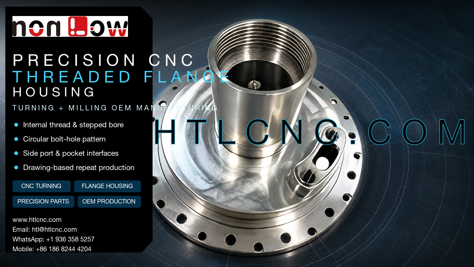
Precision CNC threaded flange housing production coordinates an internal thread, cylindrical bore, circular bolt-hole pattern and side-port interfaces in one drawing-based OEM component.
A precision CNC threaded flange housing combines turned rotational geometry with milled and drilled features that must remain related to one functional axis. The pictured component visibly includes a tall internally threaded neck, a concentric cylindrical bore, a broad circular flange, a repeated perimeter-hole pattern and a localized side-port cluster. HTL CNC supports overseas equipment builders, product-development companies and procurement teams with custom CNC machining, CNC turning, precision CNC parts, prototype validation, low-volume production and repeat OEM manufacturing from released drawings and STEP files. The photograph does not establish material grade, thread standard, tolerance, sealing duty or final application; those requirements must come from controlled customer documentation.
What Is a Precision CNC Threaded Flange Housing?
This part category joins two manufacturing families. Its neck, bore, shoulders and circular flange are primarily rotational features, while the bolt pattern and asymmetric side interfaces require indexed drilling or milling. The engineering challenge is not simply completing each feature. The finished component must preserve the required relationship among the thread axis, bore axis, flange face, mounting pattern and side ports.
For supplier review, the drawing should identify the functional datum system and distinguish locating surfaces from clearance features. Mating-part information is especially useful when the internal thread or bore receives another assembly. Without that context, a supplier cannot determine which diameters, shoulders or faces carry the most assembly risk.
Internal Thread, Bore and Shoulder Process Planning
The visible neck contains a deep internal thread above a cylindrical internal region. Depending on the released specification, the route may include rough turning, finish boring, grooving, thread cutting or thread milling. Thread form, pitch, engagement length, runout allowance and gauge method must be stated on the drawing rather than inferred from appearance.
Bore size and thread geometry should be evaluated together because both share the same body. A process plan may retain finishing stock until the part is stable, then complete the controlled diameter, shoulder and thread from a qualified setup. Where the drawing defines coaxiality, runout or perpendicularity, inspection must reference the same datum logic used for machining.
HTL's CNC turning and turn-mill machining capability is relevant when rotational features and secondary interfaces must be coordinated efficiently. The final route can use turning followed by CNC milling, or a turn-mill strategy where machine access, batch size and tolerance justify setup consolidation.
Circular Flange Face and Bolt-Hole Pattern
The broad flange provides a visible mounting surface with holes distributed around its perimeter. Drawing requirements may include face flatness, flange thickness, hole diameter, angular spacing, positional tolerance, counterbore or thread details and the relationship between the pattern and the central axis. Not every hole necessarily has the same functional importance, so the drawing should identify locating holes, fastener holes and clearance holes correctly.
A repeated circular pattern benefits from a stable angular reference. Indexed workholding, rotary positioning or coordinated multi-axis access can reduce accumulated orientation error. The choice between separate setups and integrated machining depends on part size, rigidity, quantity, inspection needs and total cost, not on axis count alone.
Side-Port Cluster and Cross-Feature Relationships
The pictured housing includes a localized side region with multiple openings and recessed geometry. These asymmetric features may require drilling, circular interpolation, boring, reaming, threading or pocket milling according to the released model. Their function cannot be confirmed from the image, but their relationship to the main bore and flange datum is a clear process-planning concern.
Where a side port intersects an internal cavity or passage, burr control and cleanliness become critical. The manufacturing plan should define access for deburring, confirmation of the internal intersection and cleaning after machining. Edge finishing must remove loose material without changing a controlled diameter, sealing shoulder or thread engagement.
Inspection Questions an OEM Buyer Should Resolve
A useful inspection plan begins with the assembly risks. Possible checks include flange-face flatness, bore diameter, thread acceptance, neck-to-flange perpendicularity, circular runout, bolt-hole position, side-port location, pocket depth and drawing-defined geometric controls. Measurement equipment can include micrometers, bore gauges, thread gauges, height systems, rotary inspection, optical systems and CMM inspection according to tolerance and access.
For supplier qualification, overseas procurement teams can request a first-article inspection report, selected dimensional results and batch records for agreed critical features. Report scope, sampling level, traceability and retention period should be defined before quotation. Every inspection record should identify the correct part number, drawing revision and production lot so evidence remains useful for repeat orders.
Prototype Review Before Low-Volume Ramp-Up
A prototype should be tested with the actual mating assembly. Engineering teams can review thread engagement, flange seating, bolt-pattern alignment, side-port access, internal clearance, fastener installation and surface-treatment allowance. Feedback should be released through updated 2D and STEP files instead of informal notes that leave revision ambiguity.
After sample approval, controlled programs, qualified fixtures, tool-life monitoring, in-process checks and revision management support repeat-order consistency. Annual demand, order frequency, delivery destination and packaging expectations help the supplier plan raw material, turning and milling capacity, outside finishing and inspection workload. HTL's prototype and low-volume CNC machining support can be used when an OEM program needs a staged route from engineering samples to repeat production.
Surface Finish, Cleanliness and Export Protection
The pictured surface does not prove a material or finishing specification. Depending on the released material and operating environment, a customer may request an as-machined condition, passivation, plating, anodizing, polishing, blasting, painting or another controlled treatment. The drawing should identify masked threads, protected bores, coating allowance, cosmetic zones and any required cleanliness level.
A flange housing can be damaged if exposed threads, mounting faces or edge features contact other parts during shipment. Thread protection, face separators, individual wrapping or formed trays may be appropriate according to geometry and route. Packaging labels should connect the part number, revision, quantity and lot with the supplied inspection documents.
RFQ Package for Drawing-Based Manufacturing
Send the released 2D drawing and STEP file with material requirements, thread specification, prototype and production quantities, annual demand, critical datums, bore and flange controls, side-port details, surface finish, inspection-document needs, packaging expectations, requested delivery date and destination. Include mating-part data when thread engagement, flange seating or port alignment depends on another component. HTL CNC can then review the actual precision CNC threaded flange housing and prepare a manufacturing, inspection and delivery plan based on controlled requirements.
Website: www.htlcnc.com Email: htl@htlcnc.com WhatsApp: +1 936 358 5257 Mobile: +86 186 8244 4204
Have a part ready for engineering review?
Send your drawing, STEP file, material and quantity directly to HTL CNC for a manufacturing quotation.