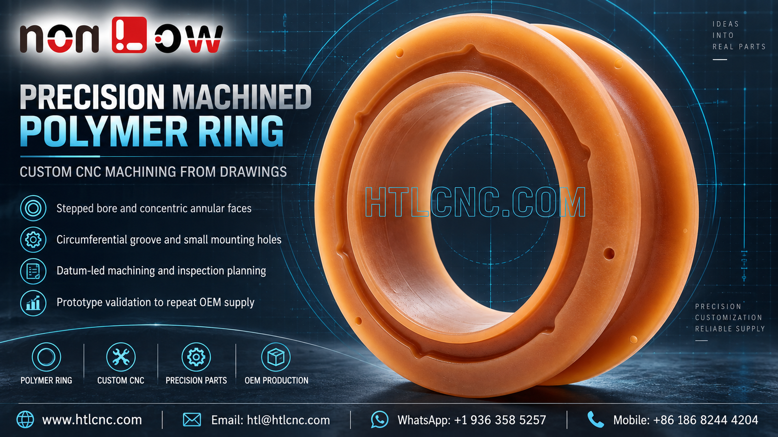
Precision machined polymer ring sourcing requires control of concentric faces, a stepped bore, annular groove, small holes and material-specific inspection from prototype to repeat OEM supply.
Precision machined polymer ring production is used when an OEM assembly needs a broad annular component with controlled concentric faces, a stepped inner bore, a circumferential groove and small holes distributed around the flange. The pictured amber ring visibly has those features, but the photograph does not confirm the resin family, grade, tolerance, temperature capability, load case or final application. Those requirements must come from the buyer's released drawing, STEP model and material specification. HTL CNC supports overseas equipment builders, product-development companies, contract manufacturers, engineers and procurement teams with custom CNC machining for polymer parts, prototype validation, low-volume builds and documented repeat production.
Why Ring Geometry Creates a Linked Datum Problem
A ring may look simple because its outside and inside boundaries are circular, yet assembly performance can depend on several related features rather than one diameter. The outer cylindrical surface, inner bore, front and rear annular faces, groove and hole pattern should be referenced to a clear datum structure. If each feature is machined or inspected independently, individual sizes may pass while the complete part still runs out, tilts or seats unevenly in the mating assembly.
The RFQ should identify which diameter locates the part, which face establishes axial seating and whether the groove is functional, clearance-related or customer-defined for another purpose. A mating-component model helps the supplier review tool access, clamping zones and inspection strategy without guessing the product's end use.
CNC Machining an Engineering Polymer Ring
Engineering polymers respond differently to cutting heat, clamping pressure and tool condition than metals. The exact route must be selected after the specified material is known. Stable workholding should support the ring without ovalizing the bore or marking critical surfaces, while sharp tools and controlled cutting conditions help limit heat buildup, smeared edges and burr formation.
A practical sequence may rough the main diameters and faces, retain material for stability, then finish the bore, annular faces and groove from a datum-controlled setup. Whether CNC turning, milling or a combined process is appropriate depends on the released geometry, hole orientation, tolerance, quantity and stock form. HTL's CNC turning and turn-mill machining capability can be reviewed alongside its custom CNC machining service when the ring combines rotational and indexed features.
Stepped Bore and Concentric Face Control
The visible central opening includes a broad internal cylindrical surface and a stepped transition near the front face. A drawing should distinguish the locating diameter from relief or clearance regions and define any required relationship between the bore axis and the seating faces. Tool deflection, interrupted support and part relaxation after unclamping can affect roundness and face runout, especially when the section is relatively thin.
Process planning should also consider edge requirements. Polymer edges may need controlled deburring without rounding a functional shoulder or enlarging a small hole. If a sharp edge, chamfer or radius is important to assembly, it should be specified rather than left to a general workmanship note.
Annular Groove and Small-Hole Features
A circumferential groove is visible on the front annular face, with several local relief shapes along its path. The image cannot establish whether this groove holds a seal, provides clearance or serves another customer-defined function. Its width, depth, radial position, bottom condition and relationship to the bore should therefore be dimensioned from functional datums.
The small holes around the ring require the same discipline. The drawing should define their size, depth or through condition, angular positions and positional relationship to the selected datum axis. Indexed milling, rotary positioning or a secondary setup may be used according to the actual requirements. Hole exits and groove intersections should be reviewed for burrs or local edge damage.
Inspection Without Distorting the Part
Inspection force matters for polymer components. Excessive contact pressure or unsupported measurement can temporarily deform a ring and produce misleading results. A risk-based plan may cover outside diameter, bore size, face thickness, step depth, groove width and depth, hole position, flatness, roundness, concentricity or runout only where the drawing requires them.
Measurement can combine calibrated hand tools, low-force bore measurement, height systems, optical methods, roundness equipment, CMM inspection or customer-approved functional gauges. The method should match the tolerance and material behavior. First-article documentation should identify the exact part number, drawing revision, material lot and measurement condition.
Material Confirmation and Handling Requirements
The amber appearance is not sufficient to identify PEEK, polyimide or any other specific resin, and HTL will not substitute a visual guess for the customer's material callout. Procurement should provide the exact material specification, approved manufacturer or equivalency rules where applicable, color requirement, certification scope and any conditioning requirement before machining begins.
Finished polymer rings may need protection from scratching, contamination, ultraviolet exposure, heat or deformation during storage and export transportation, depending on the selected resin and cosmetic zones. Packaging should prevent heavy parts from loading the ring and should keep machined faces separated from abrasive contact.
Prototype Validation Before Repeat OEM Supply
Prototype quantities allow the engineering team to verify bore fit, axial seating, groove alignment, hole-pattern orientation, assembly clearance and the proposed inspection method. If testing changes the groove, step or material requirement, the 2D drawing and STEP model should be updated together so the manufacturing and quality plans remain aligned.
After sample approval, controlled programs, documented setup references, approved material sources, first-piece checks, revision control and lot-linked inspection records support low-volume ramp-up and repeat orders. HTL's prototype and low-volume CNC machining service supports this staged qualification route.
RFQ Checklist for a Precision Machined Polymer Ring
Send the released 2D drawing and STEP file, exact material specification, prototype and production quantities, annual demand, functional bore and face datums, groove definition, hole pattern, tolerances, edge requirements, inspection-document scope, packaging, destination and target delivery schedule. Include the mating-component model when fit or alignment is critical. HTL CNC can then review the precision machined polymer ring project and propose a controlled machining, inspection and supply plan.
Website: www.htlcnc.com Email: htl@htlcnc.com WhatsApp: +1 936 358 5257 Mobile: +86 186 8244 4204
Have a part ready for engineering review?
Send your drawing, STEP file, material and quantity directly to HTL CNC for a manufacturing quotation.