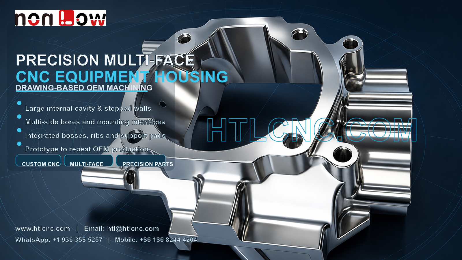
Precision multi-face CNC equipment housing production integrates a large internal cavity, stepped walls, mounting bores, ribs and side interfaces in one drawing-based OEM part.
Precision multi-face CNC equipment housing production must control features that approach the part from several directions. The pictured component visibly combines a large internal cavity, stepped wall geometry, a broad perimeter face, multiple mounting bores, local bosses, reinforcing transitions and several side-facing cylindrical interfaces. HTL CNC supports overseas OEMs, equipment builders and engineering teams with custom CNC machining, precision CNC parts, prototype development, low-volume production and repeat manufacturing from controlled drawings and STEP files. The photograph does not confirm material grade, tolerance, sealing function or final application; those requirements must come from released customer documentation.
What Makes This a Multi-Face CNC Housing?
A multi-face housing contains functional features on more than one orientation. The main cavity and upper perimeter can be accessed from the principal machining direction, while side bores, cross-holes, mounting tabs and protruding interfaces may require indexed positioning or qualified refixturing. The manufacturing plan must preserve the positional relationship between these faces rather than treat every hole as an independent feature.
For supplier qualification, buyers should identify the primary assembly datum, secondary locating surfaces and any interface that controls the final mechanism. A complete 2D drawing should define tolerances, threads, geometric controls and finish notes, while the STEP model supports access, collision and workholding review. This is the basis of reliable drawing-based custom manufacturing.
Large Internal Cavity and Stepped-Wall Machining
The dominant opening contains changing floor levels and sculpted internal walls. Roughing strategy should remove material in controlled stages while maintaining enough stiffness for later finishing. Tool diameter, projection, corner radius, chip evacuation and clamping support all influence the process route.
If a deep region requires a long-reach cutter, the supplier may need to balance access against vibration and deflection risk. Engineering teams can reduce unnecessary complexity by distinguishing functional small radii from corners that may accept a larger cutter radius. The released model and drawing, not a generic photograph-based assumption, determine the final machining sequence.
Perimeter Face, Hole Pattern and Datum Relationships
The upper perimeter includes several holes around an irregular profile. Depending on the drawing, this face may mate with another structure, carry a cover or simply provide installation points. Relevant controls can include face flatness, profile, hole position, counterbore geometry, thread depth and relationship to the internal cavity.
Inspection should follow the functional dimension chain. If several holes locate one mating component, the pattern should be evaluated as a group. If only selected holes are critical and others provide clearance, the drawing should make that distinction clear so inspection effort matches assembly risk.
Selecting 3-Axis, 4-Axis or 5-Axis CNC Machining
Some versions can be produced with 3-axis CNC machining and controlled setup changes. Indexed 4-axis or 5-axis CNC machining may be considered when side features, cross-face relationships or tool access make setup reduction valuable. Axis count alone is not a quality guarantee; the choice depends on datum transfer, rigidity, available tool length, production quantity and total manufacturing cost.
HTL's 5-axis CNC machining capability is relevant when complex equipment housings need coordinated access to several faces. For less demanding geometry, a simpler route may be more efficient. A credible quotation should explain the proposed setup logic and critical inspection points instead of merely listing machine specifications.
Integrated Bosses, Ribs and Side Interfaces
Visible bosses and transitions connect the cavity, perimeter and side structures. Their height, bore size, thread condition and position can affect the fit of attached components. Side-facing cylindrical features may require drilling, interpolation, boring, reaming, threading or profile milling according to the released requirements. Their exact function cannot be determined from appearance.
Deburring is especially important where side openings intersect cavities or threaded regions. Edge finishing must remove loose material without changing a datum shoulder, reducing thread engagement or rounding a controlled port. Cleaning should also address chips and process residue trapped in intersecting features.
Inspection Evidence for OEM Supplier Approval
A practical inspection plan may include the perimeter face, cavity depth, stepped-wall location, hole-pattern position, boss height, side-bore size and axis relationship, mounting-tab geometry and drawing-defined geometric controls. Measurement equipment can include calipers, micrometers, depth gauges, pin and thread gauges, height systems, optical equipment and CMM inspection according to access and tolerance.
Overseas procurement teams may request selected dimensional results, a first-article inspection report, material or finishing documents and batch records. Report scope, sampling frequency, traceability and document retention should be agreed before quotation. Each record should identify the exact part number, revision and production lot.
Prototype Validation and Repeat-Order Control
A prototype should be checked in the real assembly for seating, perimeter fit, internal clearance, hole alignment, side-interface access, fastener installation and finish allowance. Design feedback should be released through updated controlled files before low-volume ramp-up. Drawing confidentiality, file access and engineering-change communication can be addressed during supplier onboarding.
After sample approval, controlled programs, qualified workholding, tool-life monitoring, in-process checks and revision management support repeat production. Annual demand, batch size, delivery schedule and destination help plan raw material, machine capacity, outside finishing, inspection workload and export packaging. Buyers can review related prototype and low-volume CNC machining support when preparing a staged launch.
Surface Finish and Export Packaging
The housing may be supplied as machined or with a customer-specified treatment compatible with the released material. Potential processes include anodizing, plating, passivation, blasting, brushing, polishing, painting or another controlled finish, but no treatment should be inferred from the image. Drawings should identify masked mating faces, protected bores, plugged threads, coating allowance and cosmetic zones.
Packaging should protect the perimeter face, exposed bosses and side interfaces against impact and metal-to-metal contact. Separators, protective caps, individual wrapping or formed trays can be selected according to geometry and shipment route. Labels should connect the part number, revision, quantity and lot with the supplied quality documents.
RFQ Information for Engineering Review
Send the released 2D drawing and STEP file with material requirements, prototype and production quantities, annual demand, critical datums, cavity and hole tolerances, threads, surface finish, inspection-document needs, packaging expectations, requested delivery date and destination. Include mating-part information when the perimeter or side interfaces depend on related components. HTL CNC can then review the actual precision multi-face CNC equipment housing and develop a process and quality plan based on controlled requirements.
Website: www.htlcnc.com Email: htl@htlcnc.com WhatsApp: +1 936 358 5257 Mobile: +86 186 8244 4204
Have a part ready for engineering review?
Send your drawing, STEP file, material and quantity directly to HTL CNC for a manufacturing quotation.