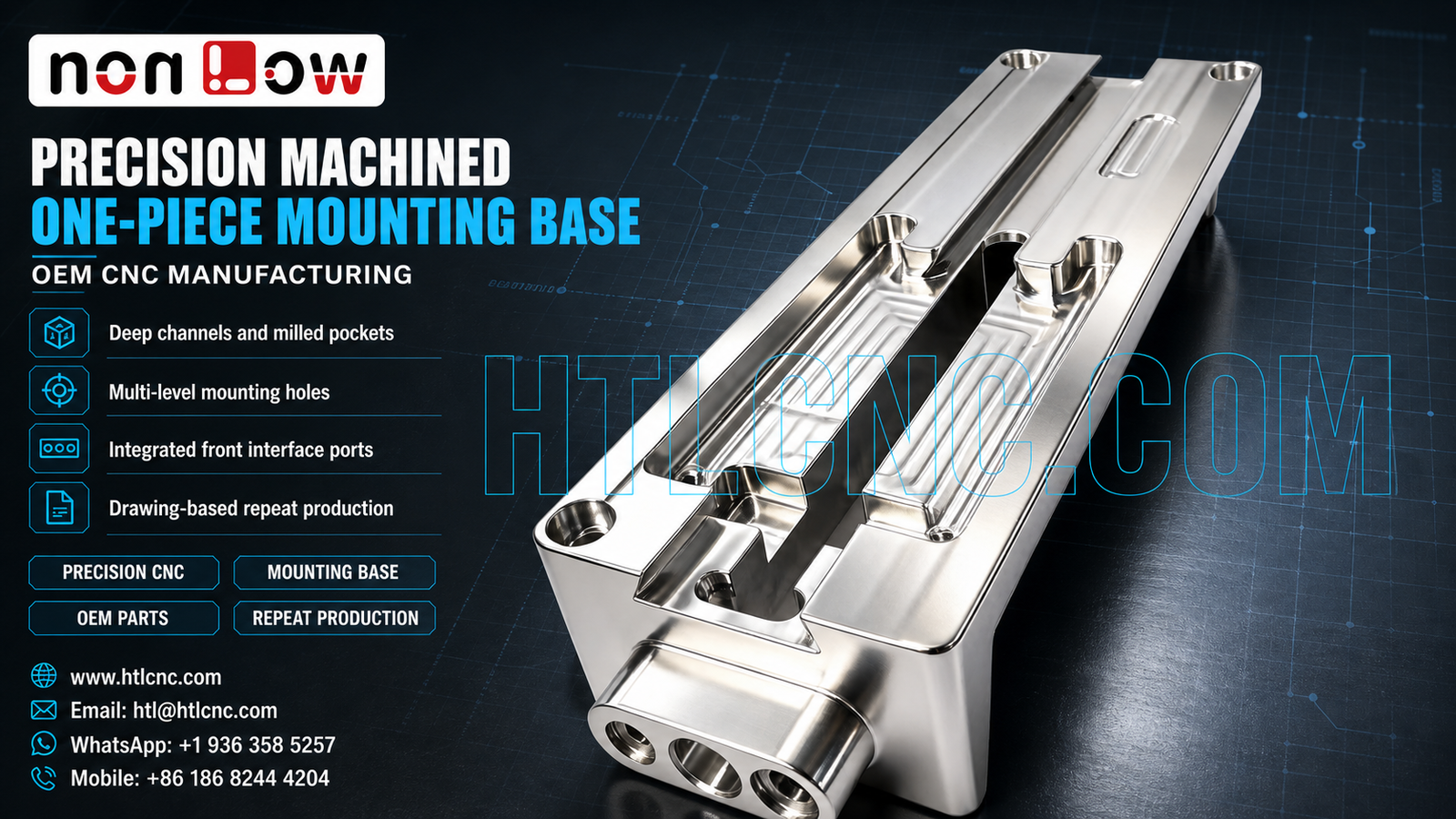
Drawing-based B2B custom CNC machining for one-piece equipment mounting bases with deep longitudinal channels, stepped pockets, multi-level mounting holes and integrated interface ports.
A precision one-piece CNC mounting base can consolidate alignment, support and interface functions into a single machined component. The visible part combines a long rectangular body, two deep longitudinal channels, stepped pocket floors, repeated mounting holes, local recesses and an integrated front boss with three circular ports. These features make datum planning, stable workholding and cross-feature inspection central to a repeatable OEM manufacturing route. The exact material, dimensions, tolerances, finish and final application must follow the customer's released files.
HTL CNC provides drawing-based custom CNC machining for overseas OEMs, product-development companies, equipment builders, contract manufacturers, engineers and procurement teams. We support engineering review, prototype validation, low-volume production and repeat production. A photograph can support discussion of visible machining features, but it cannot confirm a material grade, tolerance, certification or end use.
Why a One-Piece Mounting Base Needs a Datum-Led Process
The component's mounting holes, channel walls, pocket floors and front interface ports must function as one coordinated geometry. Measuring each feature independently is not enough when assembly depends on their relationship to a shared reference face or centerline. The released 2D drawing should identify primary, secondary and tertiary datums and state which dimensions or geometric controls govern assembly.
During supplier qualification, the engineering team should review how the part is located in each setup, how the front boss is related to the long body and how the final inspection recreates the drawing datum structure. Programs, fixture instructions and inspection records should remain linked to the approved part number and revision.
Deep-Channel and Stepped-Pocket CNC Machining
Two long open channels and several stepped regions are visible on the upper face. Deep-channel milling requires attention to tool reach, cutter rigidity, chip evacuation and remaining wall support. A controlled route may rough the major volume first, retain finishing allowance around critical faces and complete the drawing-defined channel widths, depths and transitions after the workpiece has reached a more stable condition.
Internal corner radii, bottom blends and narrow local recesses should be specified rather than inferred. Cutter selection depends on the approved radii, depth and access. Where a long channel runs beside a raised rail, balanced cutting and controlled finishing passes can reduce the risk of local deflection or inconsistent surface condition.
Multi-Level Mounting Holes and Recessed Features
The visible mounting pattern includes holes at different levels and near interrupted surfaces. Depending on the drawing, these features may require drilling, interpolation, boring, reaming, tapping, thread milling or counterboring. The correct method follows the diameter, depth, tolerance, thread requirement and positional relationship—not the visual appearance alone.
Hole-entry chamfers and deburring should remove sharp material without enlarging a locating feature or damaging an adjacent reference surface. If some holes are for location and others provide clearance, that distinction should be explicit in the drawing and inspection plan.
Integrated Front Interface Ports and Multi-Face Access
The front projection contains three circular openings on a face that is perpendicular to the main channel direction. This creates a cross-face relationship that may require controlled reclamping, indexed positioning or multi-axis access. A 3-axis process with verified datum transfer may be suitable for some designs, while 4-axis or 5-axis CNC machining can be considered when setup reduction, tool access or positional relationships justify it.
More machine axes do not automatically improve quality. The process should balance datum continuity, fixture rigidity, cutter access, handling risk, cycle time and inspection access. If the ports must align with internal passages, mating components or the longitudinal channel, those relationships should be defined and checked during first-article inspection.
Workholding for a Long, Feature-Dense Component
The part has a long footprint and several interrupted surfaces. Initial setups may use stock faces, while later operations can locate from established machined datums, soft jaws, modular supports or a dedicated fixture. Clamp positions should support rigid regions and avoid pulling the component into a temporary condition that changes after release.
Prototype quantities can use adaptable workholding while the design is being validated. After sample approval, documented fixture locations, loading sequence, tool lists and in-process checks can improve repeat-order consistency. Annual demand and expected batch size help determine whether dedicated fixturing is commercially justified.
Inspection Evidence for OEM Supplier Approval
An agreed inspection plan may cover the main reference faces, overall profile, channel width and depth, pocket levels, hole diameters, hole positions, front-port geometry, cross-face relationships, edge condition and any drawing-specified geometric controls. Calipers, micrometers, height measurement, depth tools, pin or thread gauges, bore measurement, optical equipment and CMM inspection may be selected according to tolerance and feature access.
Overseas buyers should define the documentation required with prototypes and repeat shipments. The scope may include selected dimensional results, a first-article report, material or finishing documents from the relevant source and lot-level inspection records. Each record should identify the released drawing revision and production batch.
Surface Finish, Cleanliness and Export Packaging
The component can be supplied as machined or with a customer-specified finish compatible with the released material. Anodizing, plating, passivation, blasting, brushing, polishing, painting or another treatment should be quoted only when specified. Functional datums, port interiors, threads, cosmetic zones, masking and coating allowance should be agreed before production.
Long polished faces and pocket edges can be damaged by metal-to-metal contact. Protective separation, sleeves, trays or other export packaging can help preserve cosmetic and functional surfaces. Packaging labels, part number, revision and lot identity should align with the customer's receiving process.
From Prototype Validation to Repeat Production
Prototype evaluation should verify assembly fit, channel clearance, mounting-hole alignment, front-port relationships, accessible edges and finishing assumptions. Procurement teams can also assess engineering communication, drawing confidentiality, revision control, inspection evidence, packaging and delivery performance before supplier approval.
After sample approval, controlled programs, stable workholding, defined inspection points and formal change management support low-volume ramp-up and recurring OEM orders. A complete forecast helps the supplier plan material, machine capacity, fixture investment, finishing batches and delivery schedules.
RFQ Information for Engineering Review
Send the released 2D drawing and STEP file together with the specified material, prototype and production quantities, annual demand, critical channel and port tolerances, surface finish, inspection-document requirements, packaging needs and delivery destination. HTL CNC can then review the actual geometry and propose a realistic manufacturing and quality plan.
Website: www.htlcnc.com Email: htl@htlcnc.com WhatsApp: +1 936 358 5257 Mobile: +86 186 8244 4204
Have a part ready for engineering review?
Send your drawing, STEP file, material and quantity directly to HTL CNC for a manufacturing quotation.