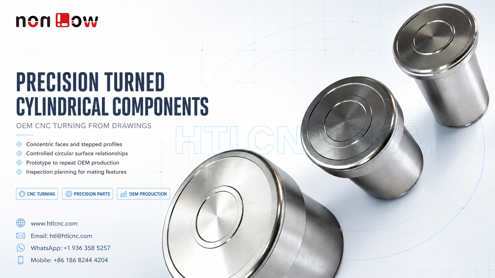
Precision turned cylindrical components depend on controlled concentric faces, stepped profiles, repeatable workholding and inspection matched to the released drawing.
Precision turned cylindrical components are used when an OEM needs circular faces, stepped outside profiles and mating diameters to remain related around one controlled axis. The pictured set visibly shows three cylindrical parts with broad machined end faces, concentric circular steps, circumferential grooves near the rim and smooth outside walls. HTL CNC supports overseas equipment builders, product-development companies, contract manufacturers, engineers and procurement teams with custom CNC turning, precision CNC parts, prototypes, low-volume production and repeat drawing-based custom manufacturing. The photograph does not establish material grade, tolerance, internal geometry, coating or final application; those requirements must come from the customer's released 2D drawing, STEP model and assembly specification.
What Makes a Cylindrical Part a CNC Turning Project?
A rotational part is not defined only by its round outside shape. Turning becomes relevant when multiple diameters, shoulders, end faces, grooves or bores must share a controlled centerline and can be produced efficiently while the workpiece rotates. The visible concentric face pattern and circumferential features are consistent with that process family, although the final route still depends on stock form, quantity, access and drawing requirements.
During supplier qualification, the OEM should identify the functional axis, mating diameters, seating face and any surface that controls axial position. A supplier cannot determine fit, sealing or load function from appearance. The released drawing should distinguish functional features from cosmetic rings and general clearance surfaces.
Concentric Faces and Stepped Profiles
The broad end face contains several circular levels. If these features locate or seat a mating component, their diameter, depth, face runout and relationship to the selected datum axis may matter more than the appearance of the individual rings. Requirements should be stated only where assembly function justifies them.
A practical process may establish the main outside diameter and end face in one setup, then finish related steps and grooves without unnecessary re-clamping. When both ends or internal features require access, the second setup needs a qualified locating method that protects the finished surface and preserves the intended axis.
Groove, Rim and Edge Requirements
The visible circumferential groove near the upper rim creates a narrow land and edge transition. The drawing should define groove width, depth, corner condition and edge break when those details affect mating, retention or appearance. If the groove is only cosmetic, that should also be clear so inspection effort remains proportional to function.
Tool selection must account for chip control, corner access and the risk of marking adjacent surfaces. Deburring should remove loose edges without rounding a functional shoulder or changing the groove profile. Surface marks from jaws, collets or handling should be controlled according to the customer's defined cosmetic zones.
Workholding and Datum Transfer
Round parts may be held with collets, soft jaws, chucks, mandrels or dedicated fixtures according to size, wall thickness, stock form and quantity. The correct method supports the part without excessive deformation and keeps the functional axis repeatable. A polished exterior does not reveal whether the part is solid, hollow or thin-walled, so fixture pressure cannot be prescribed from the photograph.
If a second operation is required, datum transfer should reference a stable diameter or face that is protected from damage. For parts that combine turned and milled details, CNC turning and turn-mill machining can be evaluated to reduce handling, but only where geometry and volume justify the route.
How Should Turned Components Be Inspected?
Inspection should follow the assembly function. A risk-based plan may include outside diameters, step diameters, overall length, face-to-shoulder distances, groove geometry, end-face flatness, runout, concentric relationships and drawing-defined surface finish. Measurement can combine micrometers, calipers, height or depth systems, bore gauges when internal features exist, runout fixtures, surface instruments and CMM methods as appropriate.
The measurement datum must match the drawing datum. A diameter can pass independently while a seating face or concentric step is incorrectly related to the functional axis. First-article records should therefore show both size and the specified relationships, linked to the correct part number and revision.
Surface Finish Must Follow the Material and Environment
The bright metal appearance does not prove a material or finishing process. Depending on the customer-specified material and operating environment, the final condition may be as-machined, polished, plated, passivated, anodized, coated or another compatible treatment. Coating thickness, masking, post-finish dimensions and cosmetic acceptance should be agreed before quotation.
Broad circular faces can reveal handling marks and uneven reflection. If appearance matters, the OEM should identify viewing surfaces, grain direction where applicable, acceptable marks and protective packaging. Functional diameters and seating faces should be separated from cosmetic requirements in both the drawing and inspection plan.
Prototype Approval Before Repeat Supply
Prototype quantities allow the engineering team to check mating fit, axial seating, concentric relationships, groove function, handling and the selected inspection method. Any pressure, sealing, wear, rotational-speed or life test requires customer-defined conditions and acceptance criteria; no performance claim can be made from the image.
After sample approval, controlled programs, qualified workholding, first-piece verification, tool-life monitoring and revision control support repeat-order consistency. HTL's prototype and low-volume CNC machining provides a staged route from engineering samples to recurring supply, while the custom CNC machining service supports drawing review and process planning.
Procurement Questions for an OEM RFQ
Buyers should ask which datum will establish the functional axis, how related diameters and faces will be completed, how the second setup will be located, which characteristics will appear in first-article records and how approved revisions will be controlled. Delivery cadence, annual demand, lot traceability, export packaging and protected surfaces should also be agreed for recurring programs.
Send the released 2D drawing, STEP file and any mating-part model with material, prototype quantity, production quantity or annual demand, functional diameters, datum structure, tolerances, surface finish, cosmetic zones, inspection-document scope, packaging, destination and target schedule. HTL CNC can then review the actual precision turned cylindrical components project and prepare a manufacturing, quality and supply plan.
Website: www.htlcnc.com Email: htl@htlcnc.com WhatsApp: +1 936 358 5257 Mobile: +86 186 8244 4204
Have a part ready for engineering review?
Send your drawing, STEP file, material and quantity directly to HTL CNC for a manufacturing quotation.