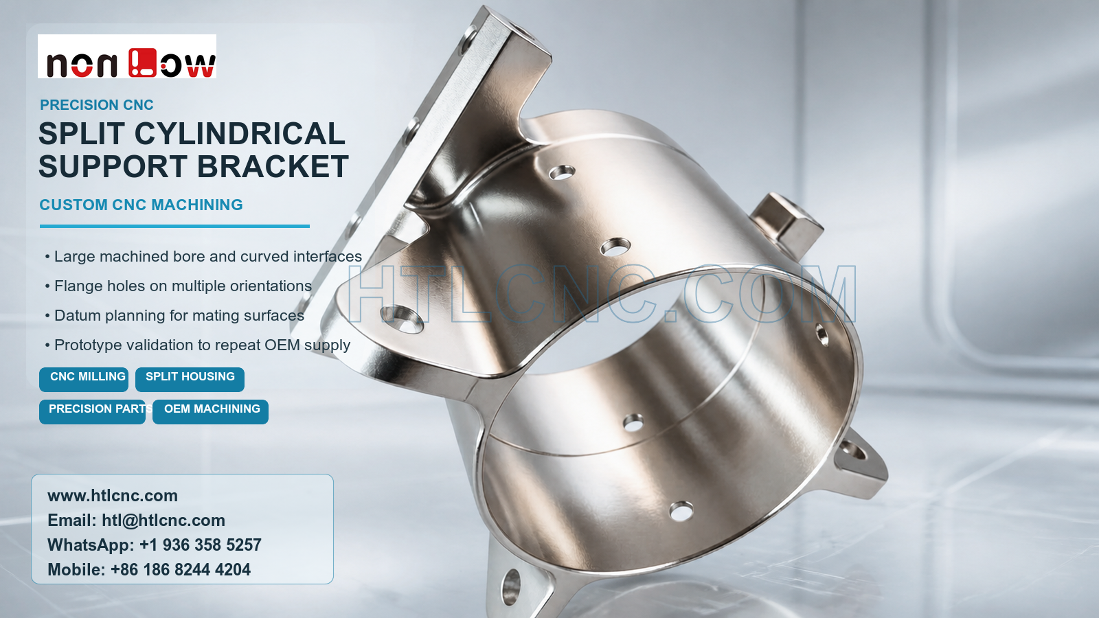
Split cylindrical support bracket custom CNC machining coordinates a large curved bore, mating shell surfaces, flange holes and multi-face mounting features for prototype and repeat OEM supply.
Split cylindrical support bracket custom CNC machining is relevant when an OEM equipment assembly needs a large curved support surface together with mating shell interfaces, projecting flanges and holes on several orientations. The pictured component visibly combines a broad cylindrical bore, a separated curved upper segment, multiple mounting tabs, counterbored or through-hole features and local side interfaces. HTL CNC provides custom CNC machining, precision CNC parts, large-bore milling, multi-face drilling, prototype validation, low-volume production and repeat drawing-based manufacturing for overseas engineering and procurement teams. The photograph does not confirm material grade, tolerance, surface treatment, load capacity or final use; those requirements must be defined in the customer's released 2D drawing, STEP model and assembly information.
What Is a Split Cylindrical Support Bracket?
A split cylindrical support bracket uses two or more curved interfaces to locate, support or retain a round mating component. The visible geometry suggests that bore size, roundness, shell alignment and flange position may interact, but the specific assembly function cannot be inferred from the image. The OEM drawing should state whether the bore is a clearance surface, locating diameter, clamping interface or noncritical envelope.
For quotation, the buyer should provide the complete assembly model and identify which shell faces meet, which fasteners close the split, and which mounting tabs establish the bracket position in the equipment. Without that context, a supplier can price visible machining but cannot responsibly define functional inspection.
How Should the Large Bore and Split Interface Be Related?
The datum plan should begin with the surfaces that position the bracket in the final assembly. From those references, the drawing can control the large bore, the split or mating faces, flange holes and projecting tabs. If bore geometry is only meaningful after the segments are assembled, the OEM should specify the assembly condition, fastener state and measurement method.
Machining the curved interface may involve a qualified setup that preserves the relationship between the bore and external mounting features. Depending on part size and access, the route may use 3-axis milling with controlled refixturing, indexed 4-axis work or 5-axis CNC machining. The selected process should follow datum continuity and inspection access, not axis count alone.
Curved-Surface Machining and Toolpath Control
Large internal radii require stable cutter engagement and consistent surface generation. Tool diameter, step-over, tool reach and finishing direction influence scallop pattern, local blending and cycle time. If the bore has a drawing-defined fit or surface requirement, the process plan should reserve controlled finish stock and verify the diameter in the specified assembly condition.
The exterior curved surface and local transitions also need practical radii. Unnecessarily sharp internal blends can force smaller tools and longer reach, increasing tool deflection and cycle time. Design review should distinguish cosmetic blends from functional shoulders before programs and fixtures are finalized.
Multi-Face Flange Holes and Mounting Tabs
The pictured bracket includes holes on the curved shell, a linear flange and several projecting tabs. The released drawing should distinguish clearance holes, threaded holes, counterbores, locating holes and noncritical access features. Hole position, depth, thread engagement, edge distance and relationship to the primary datums should be explicit where they affect assembly.
Features approached from different directions may require indexing or refixturing. A qualified process must reproduce the same references in each setup and leave enough access for drilling, deburring and inspection. Where a hole breaks into the large bore or another surface, the drawing should define edge-break limits so burr removal does not enlarge a functional diameter.
Inspection Questions for Supplier Qualification
A risk-based inspection plan may cover the mounting datum, overall profile, bore size and form, split-face condition, flange position, hole size and position, threads, tab geometry and drawing-defined geometric controls. Calibrated bore gauges, height measurement, pin or thread gauges, optical systems, CMM probing and customer-approved assembly fixtures may be combined according to feature access and tolerance.
First-article documentation should identify the part number, revision, measurement condition and any temporary assembly hardware used during inspection. If the bore must be checked after joining two segments, the report should record that method. For repeat OEM orders, material records, finishing documents and lot inspection reports should remain linked to the released revision and purchase order.
Surface Finish, Edge Control and Export Packaging
The bright metallic appearance does not establish a material or treatment. After the alloy or other material is confirmed, the buyer may specify an appropriate finish such as anodizing, plating, passivation, blasting, polishing, painting or another process. Bore surfaces, mating faces, threads and coating-sensitive fits should be marked for masking or post-finish verification where necessary.
Projecting tabs and curved edges can be vulnerable during handling. Packaging may use individual separation, formed supports or protective covers to prevent contact damage. The RFQ should also state cosmetic zones, permitted edge breaks, cleanliness expectations and export destination so handling and packing are included in the supply review.
Prototype Validation to Repeat Production
Prototype quantities allow the OEM to check mating diameter, closure of the split interface, mounting-hole alignment, fastener access and installation into the surrounding equipment. Any load, vibration or retention test requires customer-defined conditions and acceptance criteria; performance must not be inferred from appearance.
After sample approval, controlled programs, qualified fixtures, first-piece checks, tool-life monitoring and formal revision control support low-volume ramp-up and repeat production. HTL's custom CNC machining service supports manufacturability review and process planning, while prototype and low-volume CNC machining provides a staged path from engineering samples to recurring OEM supply.
RFQ Package for a Split Cylindrical Support Bracket
Send the released 2D drawing, STEP file and relevant assembly model. Include material, prototype and production quantities, annual demand, bore and mating-interface requirements, datum scheme, hole and thread definitions, critical tolerances, surface finish, inspection-document scope, assembly or functional validation requirements, packaging, destination and target delivery. HTL CNC can then review the actual split cylindrical support bracket custom CNC machining project with a defined process and inspection scope.
Website: www.htlcnc.com Email: htl@htlcnc.com WhatsApp: +1 936 358 5257 Mobile: +86 186 8244 4204
Have a part ready for engineering review?
Send your drawing, STEP file, material and quantity directly to HTL CNC for a manufacturing quotation.