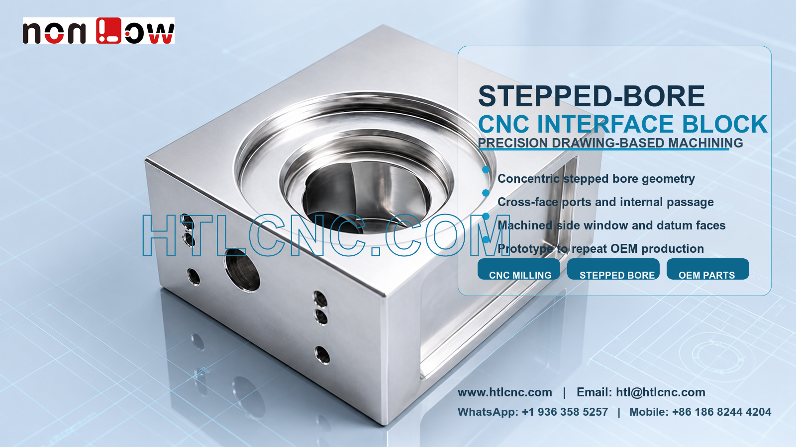
A stepped-bore CNC interface block combines concentric circular levels, an intersecting internal passage, cross-face ports and a machined side window in one precision OEM component.
A stepped-bore CNC interface block is a compact precision component in which several functional interfaces are machined into one block. The pictured part visibly combines a large multi-level circular bore, an intersecting internal passage, a front circular port, repeated smaller front holes and a rectangular side window. HTL CNC provides custom CNC machining and drawing-based OEM manufacturing for equipment builders, product-development teams and overseas procurement organizations that need precision CNC parts from prototype validation through low-volume production and repeat orders. Material grade, fits, tolerances and final use cannot be determined from the photograph and must follow the customer's released drawings and STEP file.
What Must Be Defined for a Stepped-Bore Interface Block?
The main bore is not a single diameter. It contains several circular levels that may require independent diameters, depths, shoulders and surface requirements. A complete drawing should identify the functional datum, each step size, transition radius or chamfer, and any geometric relationship between the bore and the exterior faces.
If the bore receives a shaft, sleeve, seal, bearing or another component, the mating data should be included in the RFQ. This allows engineering review to distinguish a locating diameter from a clearance region and prevents unnecessary precision from being applied to non-functional surfaces.
Concentricity, Depth and Shoulder Control
Concentric stepped features are commonly produced by circular interpolation, boring, reaming or another route selected from size, depth, material and tolerance. The important requirement is the relationship among the steps, not only each individual diameter. Inspection may need to address concentricity, runout, axis position, shoulder depth or perpendicularity when specified.
Tool access and chip evacuation become more important as the bore deepens. A staged operation can leave finishing stock before the controlled steps and shoulders are completed. No specific fit or tolerance should be claimed from the image; the released drawing remains the acceptance authority.
Intersecting Internal Passage and Cross-Face Ports
The visible internal passage enters the central bore from another direction. Side and front ports create cross-face relationships that may require controlled refixturing or indexed multi-axis access. Their locations should be dimensioned from a stable datum system so the intersection occurs in the intended region.
Intersecting holes also create deburring and cleanliness risks. Loose edges inside the bore can affect assembly or damage a mating component. The process plan should define how hidden intersections are inspected and cleaned without rounding a controlled shoulder or altering thread engagement.
Side Window and Exterior Datum Faces
The rectangular side window and broad machined faces provide additional access and mounting geometry. Depending on the drawing, the side window may require profile control, corner radii, depth and position relative to the main bore. The exterior faces can serve as workholding and inspection datums if their functional role is confirmed.
A compact block may be machined with 3-axis CNC milling and qualified setup changes. Indexed 4-axis or 5-axis CNC machining can be considered when the bore, ports and window must remain closely related and setup reduction improves stability. The selected route depends on datum transfer, tool reach, rigidity, batch size and cost. Buyers can review HTL's custom CNC machining capability when preparing the technical package.
Inspection Evidence for Supplier Qualification
A functional inspection plan may include step diameters, bore depths, shoulder positions, bore axis, front-port location, small-hole patterns, side-window profile, exterior-face relationships and drawing-defined geometric controls. Suitable equipment can include micrometers, bore gauges, depth gauges, pin and thread gauges, height measurement, optical systems and CMM inspection according to access and tolerance.
Overseas OEMs may request a first-article inspection report, selected dimensional results or batch records for critical features. The report scope, sampling level, traceability and document-retention period should be agreed before quotation. Each record should identify the controlled part number, revision and production lot.
Prototype Validation Before Repeat Production
A prototype should be evaluated with the real mating components. Engineering teams can check stepped-bore fit, shoulder seating, cross-port alignment, side-window clearance, fastener access, edge condition and finish allowance. Any design change should be released through updated 2D and STEP files before low-volume ramp-up.
After approval, qualified programs, repeatable workholding, tool-life monitoring, first-piece checks and revision management support repeat-order consistency. Annual demand, order cadence and delivery destination help plan stock, fixture investment, machine capacity, inspection workload and export packaging. Related prototype and low-volume CNC machining support can be considered during supplier onboarding.
Surface Finish and Protective Handling
The block may be supplied as machined or with a customer-specified treatment compatible with the released material. Potential options include anodizing, plating, passivation, blasting, brushing, polishing, painting or another controlled finish, but the image does not identify the correct process. Drawings should define masked bores, protected datum faces, thread treatment, coating allowance and cosmetic zones.
The stepped bore and exposed edges require protection during handling and international shipment. Caps, separators, individual wrapping or formed trays can reduce impact and metal-to-metal contact. Packaging labels should connect part number, revision, quantity and lot to the inspection documentation.
RFQ Information for Engineering Review
Send the released 2D drawing and STEP file with material requirements, prototype and production quantities, annual demand, critical step diameters and depths, datum relationships, threads, surface finish, inspection-document needs, packaging expectations, requested delivery date and destination. Include mating-part data when the stepped bore or cross-face ports depend on related components. HTL CNC can then review the actual stepped-bore CNC interface block and prepare a manufacturing and quality plan based on controlled requirements.
Website: www.htlcnc.com Email: htl@htlcnc.com WhatsApp: +1 936 358 5257 Mobile: +86 186 8244 4204
Have a part ready for engineering review?
Send your drawing, STEP file, material and quantity directly to HTL CNC for a manufacturing quotation.