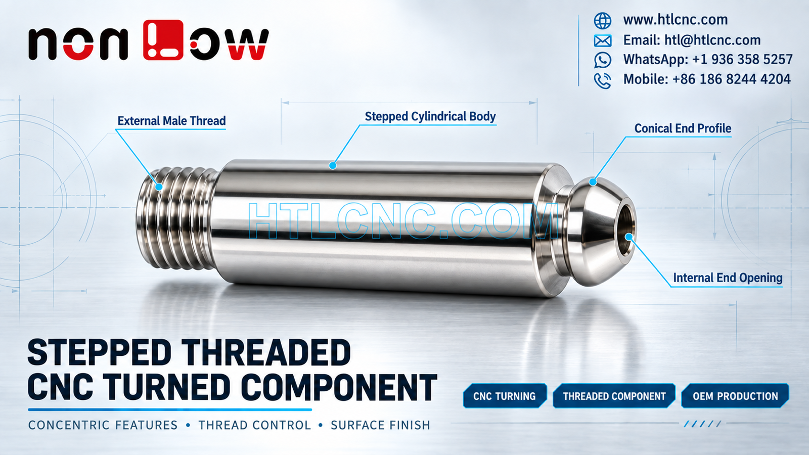
A stepped threaded CNC turned component combines an external male thread, long cylindrical body, shoulder transitions, a conical end profile and an internal opening on one rotational axis.
A stepped threaded CNC turned component concentrates several rotational features into one compact part: an external male thread, a long cylindrical body, multiple shoulder transitions, a rounded or conical terminal profile and a visible internal end opening. The source image includes several different precision parts; this article addresses only the selected horizontal turned component shown in the poster. The photograph does not establish the material grade, thread standard, fit, tolerance, coating or final application. Those requirements must come from the buyer's released 2D drawing, STEP model and assembly specification. HTL CNC supports overseas OEMs, equipment builders and product-development teams with drawing-based CNC turning, prototypes, low-volume production and repeat supply.
Start the RFQ with the Thread Specification
A male thread cannot be quoted or inspected from appearance alone. The drawing should identify the thread system, nominal size, pitch, class or tolerance, thread length, start condition, runout, root relief and required gauge method. If the thread engages after coating or plating, the drawing should state whether acceptance applies before or after finishing.
Thread notes should also distinguish a functional thread from a cosmetic representation in the 3D model. HTL's CNC turning and turn-mill machining service uses the released specification to select tooling, cutting parameters and verification methods.
Keep the Cylindrical Body and Shoulders on One Axis
The long smooth body includes several diameter changes near the thread and terminal end. The RFQ should define the finished diameters, shoulder positions, transition radii, chamfers and any runout or coaxiality requirements. Chained axial dimensions can accumulate; a functional datum face or baseline scheme is often clearer when several shoulders control assembly length.
A single turning setup may preserve concentricity between external features when stock access allows. Secondary operations, cutoff, reversal or backside work should include a controlled method for locating the existing axis. The process plan should protect finished diameters from chuck marks or transfer damage.
Internal End Opening and Wall Relationship
A visible opening is present at the terminal end, but the image does not reveal its complete depth, internal steps, thread status or function. The drawing should specify opening diameter, depth, bottom geometry, any internal thread and the minimum wall condition around the conical profile.
Internal features may require drilling, boring, reaming or threading according to size and tolerance. Inspection can use pin gauges, bore gauges, depth tools or other approved methods. If the internal opening must remain concentric with the outside body, that relationship needs an explicit geometric control.
Conical End Profile and Blend Transitions
The end profile visibly combines a neck, shoulder and rounded or conical outer surface. The 2D drawing should define the profile with angles, radii or controlled contours rather than relying only on a rendered model. Sharp transitions may create tool-access or burr risks, while broad blends can change the functional envelope.
When the terminal profile is cosmetic, a visual standard and acceptable turning marks should be agreed. When it is functional, profile measurement or a customer-approved gauge may be more useful than a general surface-finish statement.
Process Planning for CNC Turning and Secondary Features
Most visible geometry is rotational and is compatible with CNC turning. The complete model may still contain flats, cross holes, drive features or other details not visible in the selected view. These can require live-tool turning, a second machine or controlled refixturing.
HTL's custom CNC machining service reviews the full drawing before choosing a route. Machine selection follows geometry, tolerance, quantity and inspection needs; a more complex machine is not automatically the better process.
Thread, Diameter and Length Inspection
A risk-based first-article report may cover thread gauge acceptance, thread length, major or pitch diameter when specified, body diameters, shoulder positions, overall length, terminal profile, internal opening and drawing-defined runout or concentricity. Measurement methods should match the tolerance and feature accessibility.
Typical equipment may include calibrated micrometers, thread gauges, pitch tools, optical systems, depth instruments, bore gauges and CMM equipment. The inspection record should identify part number, revision, production lot and measuring equipment so results remain traceable for repeat orders.
Surface Finish and Coating Allowance
The highly reflective appearance does not prove stainless steel, chrome plating, nickel plating, polishing or another material or treatment. The RFQ should provide the exact material standard and condition, permitted substitutions, heat treatment, finish process, coating thickness, masking zones, cosmetic criteria and certificate scope.
Threads, close-fit diameters and internal openings can be affected by coating buildup. Buyers should state which surfaces are masked and which features require post-finish verification. Handling and packaging should prevent contact marks on approved cosmetic or sealing surfaces.
Prototype Assembly Validation
Prototype parts allow the OEM team to confirm thread engagement, shoulder seating, insertion depth, body clearance, terminal-end access and internal-opening compatibility with actual mating components. Any design change should update both the 2D drawing and STEP model under a controlled revision.
HTL's prototype and low-volume CNC machining service supports engineering samples before recurring releases. If torque, pressure, sealing or load performance matters, the customer should provide the applicable test method and acceptance criteria; these functions are not inferred from the photograph.
Repeat Production and Supplier Qualification
For repeat production, qualified programs, controlled tooling, first-piece checks, gauge calibration and tool-life rules help preserve thread form, diameter and shoulder position. Supplier qualification may also address drawing confidentiality, obsolete-revision quarantine, inspection-document scope, corrective-action records and delivery planning.
Small polished components require packaging that prevents metal-to-metal contact and thread damage. Thread protectors, separators, individual sleeves or formed trays may be selected from the actual finish and shipment route. Labels should identify part number, revision, quantity and production lot.
RFQ Checklist for a Stepped Threaded CNC Turned Component
Send the released 2D drawing and STEP file, mating-part information, exact material, prototype and production quantities, annual demand, external thread specification, body diameters, shoulder positions, terminal profile, internal-opening details, tolerances, geometric controls, edge breaks, surface finish, inspection-document scope, packaging, destination and target schedule. HTL CNC can then prepare a controlled turning, inspection and repeat-supply plan for the stepped threaded CNC turned component.
Website: www.htlcnc.com Email: htl@htlcnc.com WhatsApp: +1 936 358 5257 Mobile: +86 186 8244 4204
Have a part ready for engineering review?
Send your drawing, STEP file, material and quantity directly to HTL CNC for a manufacturing quotation.