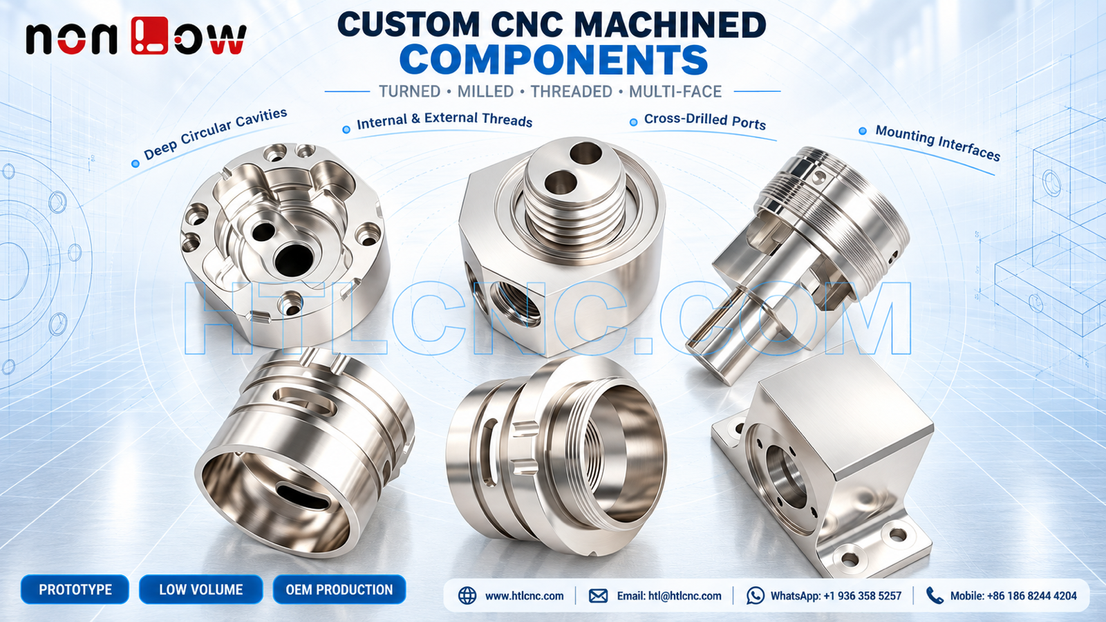
Threaded CNC machined components combine internal and external threads with cross-drilled ports, deep cavities, side windows and mounting interfaces that require feature-specific process and inspection planning.
Threaded CNC machined components frequently combine rotational and prismatic features in the same sourcing package. The pictured set visibly includes six different parts with internal or external threads, circular cavities, side ports, cross holes, windows, recessed profiles and mounting faces. Their exact materials, thread standards, tolerances, finishes and applications cannot be established from the image; those requirements must come from released 2D drawings, STEP models and assembly specifications. HTL CNC supports overseas OEMs, product-development companies, equipment builders, engineers and procurement teams with drawing-based custom CNC machining, prototypes, low-volume production and repeat supply.
Classify Every Thread Before Selecting the Process
An RFQ should identify each thread by standard, nominal size, pitch, class or tolerance, engagement length, start condition, runout and acceptance method. Rendered models often show only simplified thread geometry, so the released drawing must remain authoritative.
External threads on cylindrical bodies may be produced in a turning sequence, while internal threads in ports or housings may require tapping, thread milling, single-point cutting or another drawing-approved method. The route depends on diameter, depth, material, access, quantity and required gauge condition.
Relate Threads to Functional Faces and Axes
A thread can pass a gauge and still create an assembly problem if its axis is incorrectly located relative to a seat, bore or mounting face. Drawings should define the datum scheme and any positional, perpendicularity, runout or coaxial relationship that controls mating geometry.
For round parts, a primary bore or turned diameter may establish the axis. For the visible rectangular mounting block, the base and side interface may be more appropriate functional references. HTL's custom CNC machining service reviews these relationships before deciding setup order and workholding.
Cross-Drilled Ports Need Intersection Control
Several components visibly include side ports or holes that intersect a larger internal feature. These intersections affect tool access, burr formation, chip evacuation and inspection. The drawing should state port diameter, thread status, depth, angular position, breakthrough condition and required edge treatment.
After cross drilling or threading, an internal burr may remain beyond direct line of sight. A controlled deburring and cleaning plan should identify how the intersection is accessed and verified without rounding a functional shoulder or damaging a thread crest.
Deep Cavities and Side Windows Change Tool Access
The set includes deep circular cavities, side windows and recessed profiles. Long tool reach and restricted holder clearance can reduce rigidity. Roughing should leave support where thin walls or interrupted rings may move during final passes.
Internal corner radius, floor depth, window width and wall thickness should be defined on the drawing. These features may be produced by CNC milling, turning, turn-mill machining or controlled secondary setups depending on the dominant geometry. HTL's CNC turning and turn-mill machining service can be evaluated when concentric and side features benefit from coordinated processing.
Separate Rotational Parts from Prismatic Mounting Parts
The visible component family includes round bodies as well as a rectangular mounting block. Rotational parts may start from bar, tube, forging or prepared stock according to specification, while prismatic parts may require milling from block stock or near-net material. Appearance alone does not determine the stock route.
A mixed purchase package should retain a separate traveler, program, fixture and inspection plan for every part number. Compatible operations may be grouped for production planning, but revision and acceptance records must not be combined across different geometries.
Choose Multi-Axis Access Only Where It Reduces Risk
Cross ports, angled access and features distributed around cylindrical bodies may benefit from indexed 4-axis work, live tooling or 5-axis CNC machining. Other parts may be more stable with conventional turning followed by a qualified milling setup.
The best process minimizes uncertain datum transfer while maintaining rigid clamping and measurable references. Machine capability should be matched to the released tolerance and annual demand rather than selected from appearance alone.
Build a Thread and Port Inspection Matrix
For supplier qualification, a feature matrix can list every internal and external thread, its gauge requirement, inspection stage and coating condition. It can separately list port diameter, position, breakthrough, depth and edge acceptance. This structure prevents a general note from obscuring part-specific requirements.
Typical verification may use GO/NO-GO thread gauges, plug gauges, bore gauges, depth tools, optical equipment, height systems and CMM inspection. Where thread position or axis relationship matters, the agreed method must evaluate more than simple gauge entry. Reports should identify part number, revision, production lot and measuring equipment.
Confirm Material, Finish and Post-Finish Fit
The polished silver appearance does not prove aluminum, stainless steel, nickel plating, chrome plating or another material or finish. The RFQ should specify the exact material standard and condition, heat treatment, surface process, coating thickness, masking zones, cosmetic criteria and certificate scope.
Coating buildup can alter internal threads, external threads, bores and seating faces. The drawing should state whether dimensions and thread acceptance apply before or after finishing. Thread protection and post-finish gauging should be included in the production plan where required.
Prototype Assembly and Repeat-Order Control
Prototype quantities allow the buyer to validate thread engagement, port alignment, cavity clearance, mounting-face contact and fastener access with actual mating components. If testing changes a thread, opening or datum, both the drawing and STEP model should be revised together.
HTL's prototype and low-volume CNC machining service supports engineering samples and pilot batches. After approval, qualified programs, controlled fixtures, first-piece inspection, tool-life rules and formal revision control help maintain repeat-order consistency.
Packaging and Identification for Mixed Components
Threaded parts require protection from impact and metal-to-metal contact. Caps, sleeves, individual bags, separators or formed trays may be selected according to geometry and finish. The packaging plan should prevent heavier parts from striking thread starts, cavity rims or approved cosmetic faces.
Every package should show part number, revision, quantity and lot identity. Procurement teams should also provide annual demand, release cadence, destination and requested inspection documentation so machining, finishing, packaging and export delivery can be planned together.
RFQ Checklist for Threaded CNC Machined Components
Send a released 2D drawing and STEP file for every part, plus a part-number and revision matrix, exact material, prototype and production quantities, annual demand, internal and external thread specifications, cross-port details, cavity and window geometry, functional datums, tolerances, finish, inspection-document scope, cleanliness, packaging, destination and target schedule. HTL CNC can then prepare a controlled machining, inspection and supply plan for the threaded CNC machined components.
Website: www.htlcnc.com Email: htl@htlcnc.com WhatsApp: +1 936 358 5257 Mobile: +86 186 8244 4204
Have a part ready for engineering review?
Send your drawing, STEP file, material and quantity directly to HTL CNC for a manufacturing quotation.