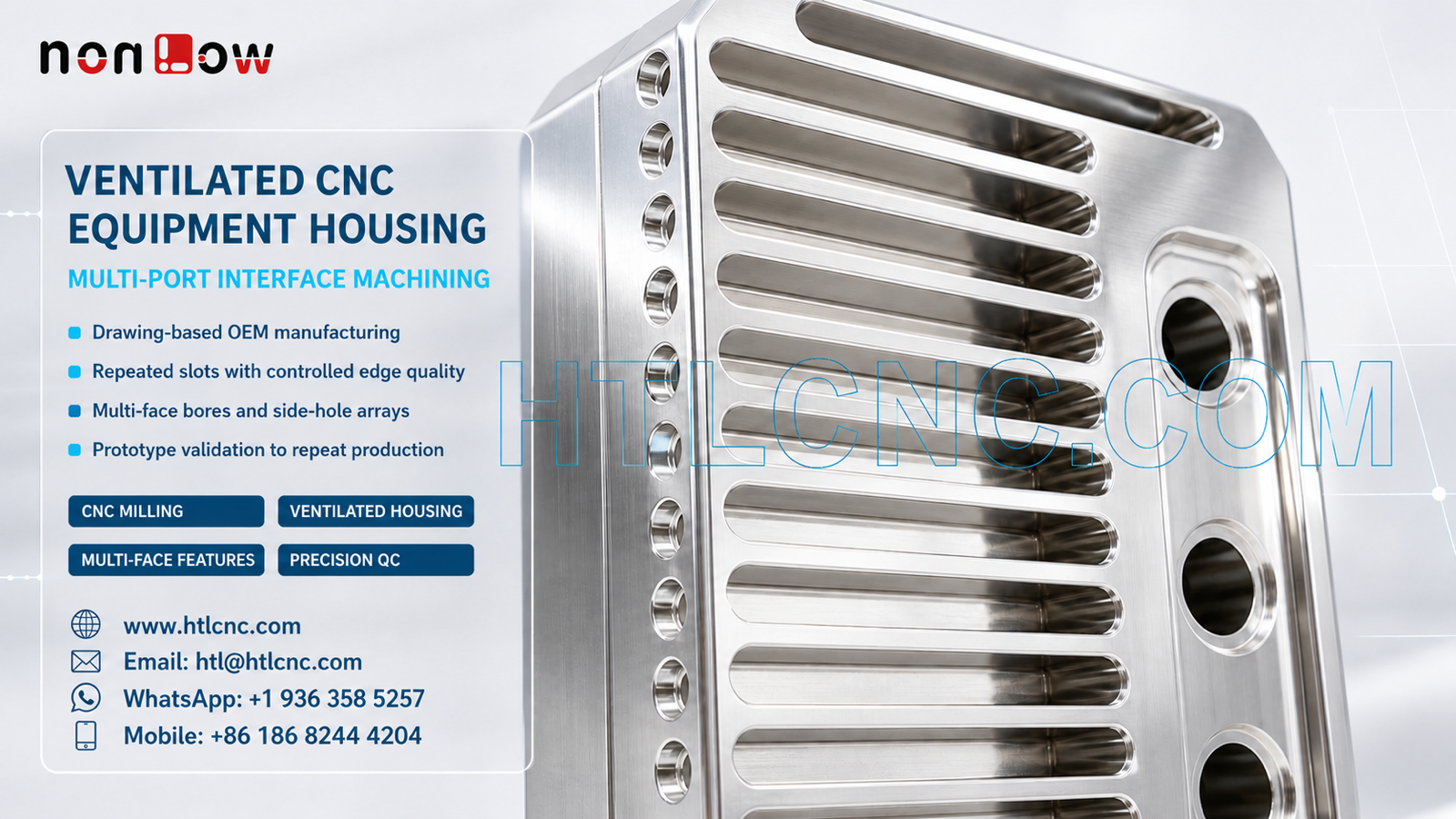
Drawing-based B2B CNC manufacturing for ventilated equipment housings with repeated through-slots, large interface bores, side-hole arrays and controlled multi-face relationships.
Ventilated equipment housings often combine airflow openings, assembly interfaces and mounting features within one machined body. The component shown here has a dense series of long through-slots across the front face, three large circular interface bores, a vertical array of smaller side holes and chamfered external corners. For an OEM sourcing program, the manufacturing challenge is to keep these features related to the released datums while maintaining controlled edges and a consistent visible finish.
HTL CNC provides drawing-based custom CNC machining for overseas equipment manufacturers, product-development companies, contract manufacturers, engineers and procurement teams. The material, dimensions, tolerances, surface treatment and final application must follow the customer's released 2D drawing, STEP model and approved sample; they cannot be confirmed from a photograph.
Supplier Qualification for a Multi-Feature Housing
A complete RFQ should include the released STEP file, controlled 2D drawing, specified material, prototype quantity, expected batch size or annual demand, critical characteristics, finishing notes, inspection-document requirements, packaging expectations and delivery destination. This allows engineering and purchasing teams to compare suppliers against the same technical and commercial scope.
Supplier onboarding should also define drawing confidentiality, revision ownership, sample-approval criteria and the change-release process. Programs, fixture references and inspection records should remain linked to the approved revision so recurring orders do not drift from the qualified sample.
Repeated Through-Slots and Edge Control
The long openings are through-slots rather than decorative surface grooves. Their width, pitch, end radii, depth and relationship to the housing perimeter must therefore follow the drawing. Tool selection and cutting direction should support repeatable slot geometry while controlling burr formation along both entry and exit edges.
Because many slots remove material from one broad face, the process plan should consider remaining stiffness as machining progresses. Balanced roughing, suitable support and controlled finishing passes can reduce vibration and help preserve the surrounding face. Deburring must remove sharp material without widening the openings or rounding drawing-defined edges.
Large Interface Bores and Side-Hole Arrays
Three large circular openings occupy the adjacent interface region, while smaller holes repeat along the side face. These features may require drilling, interpolation, boring, reaming or threading according to the released specifications. Their exact function must not be inferred from appearance.
The critical issue is the drawing-defined relationship between the bores, side-hole array and primary housing faces. Controlled reclamping, indexed positioning or multi-axis access may be used depending on datum structure, cutter clearance and quantity. Machine selection should be justified by the actual tolerance relationships rather than by the number of visible faces alone.
Workholding and Datum Continuity
Workholding should locate the housing from stable reference surfaces without forcing the broad slotted face away from its free-state condition. Initial operations may establish datum faces and major interface geometry before repeated slots and side features are completed. The sequence should preserve enough support around sensitive regions until final machining is finished.
Prototype fixtures can remain adaptable while engineering changes are open. Once the sample is approved, documented support points, jaw locations, loading instructions and program revisions can improve repeatability across low-volume ramp-up and annual purchasing schedules.
Inspection Planning for OEM Release
The agreed inspection plan may cover overall profile, slot width and pitch, opening length, bore diameters, side-hole position, chamfer condition and relationships between controlled faces. Calipers, micrometers, height measurement, pin or thread gauges, optical equipment and CMM inspection may be used according to feature geometry and drawing tolerances.
Overseas buyers should state whether prototypes or repeat shipments require selected dimensional results, a first-article report, material or finishing documents, and batch inspection records. These deliverables should be included in the RFQ and purchase order rather than requested after production.
Surface Finish, Cleaning and Export Packaging
The housing may be supplied as machined or with a customer-specified treatment compatible with the released material. Anodizing, plating, passivation, blasting, brushing, polishing, painting or another process should be considered only when defined by the RFQ. Coating allowance, masked interfaces, thread protection and cosmetic acceptance criteria need review before quotation.
Through-slots and holes must be cleaned so chips, media and residue are not trapped inside the housing. Protective separation, trays or other export packaging can help preserve visible faces and machined edges during international transport. Labels and batch identification should match the customer's receiving and revision-control requirements.
From Prototype Validation to Repeat Orders
Prototype quantities allow the engineering team to check slot edges, interface alignment, assembly access, dimensional relationships and finishing assumptions. Procurement teams can simultaneously assess response time, confidentiality, documentation, packaging and delivery performance before approving the supplier for recurring orders.
After sample approval, controlled programs, repeatable workholding, defined inspection points and change management support consistent repeat production. Forecasts or annual demand help plan material purchasing, machine capacity, fixture investment and delivery schedules.
RFQ Information for Engineering Review
Send the released 2D drawing and STEP file together with the specified material, prototype and production quantities, annual demand, critical tolerances, bore or thread requirements, surface finish, inspection-document scope, packaging needs and delivery destination. HTL CNC can then review the actual feature relationships and prepare a realistic manufacturing proposal.
Website: www.htlcnc.com Email: htl@htlcnc.com WhatsApp: +1 936 358 5257 Mobile: +86 186 8244 4204
Have a part ready for engineering review?
Send your drawing, STEP file, material and quantity directly to HTL CNC for a manufacturing quotation.