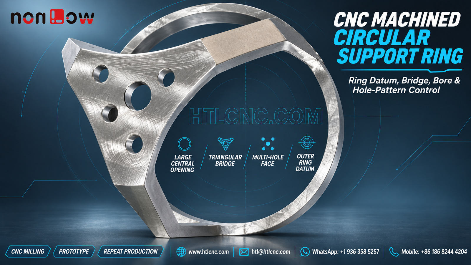
A CNC machined circular support ring combines a large central opening, a reinforced bridge, stepped arms and a multi-bore face that must remain aligned to the outer ring datum.
A CNC machined circular support ring can integrate a large central opening, one reinforced bridge, stepped connecting arms and a multi-bore face within a single open structure. The selected photograph supports those visible geometric facts, but it does not establish the material grade, dimensions, tolerances, finish, load capacity or final application. HTL CNC provides drawing-based custom CNC machining for overseas OEMs, equipment builders, product-development teams and procurement organizations that need controlled prototypes, low-volume production and repeat supply.
Qualify the Part from Its Functional Interfaces
Before requesting a quotation, the buyer should identify what passes through the large opening, which ring surface locates the assembly, what the bridge contacts and which bores receive mating hardware or alignment features. A simplified surrounding envelope helps the supplier understand clearance and seating without exposing unrelated product details.
Send the released 2D drawing and STEP model together with exact material and condition, quantities, annual demand, tolerances, finish, inspection-document scope, packaging and destination. HTL's custom CNC machining service uses those inputs to review stock strategy, setup access, workholding and measurement needs.
Choose the Outer Ring or a Machined Face as the Primary Datum
The part offers several possible references: the outside ring, the large internal opening, broad machined faces and local bridge surfaces. The drawing should select the functional primary datum rather than allowing the process plan to infer one from appearance. If the outside ring controls installation, its profile and relationship to the bridge must be measurable.
If a broad face seats against another component, flatness and the ring's perpendicular relationship to that face may matter more than a cosmetic outside diameter. Datum targets can be useful when the structure has limited continuous surface. The supplier and buyer should agree how the part is supported during inspection.
Treat the Large Opening as a Controlled Structural Profile
The central opening dominates the component but is not a simple isolated bore because the bridge and stepped arms interrupt the surrounding wall. The drawing should define its diameter or profile, local transitions, edge breaks, minimum remaining section and relationship to the outer ring datum.
Depending on the actual geometry, inspection may use CMM points or scanning, an optical system, a profile template or a customer-approved functional master. A single caliper measurement cannot prove the complete opening shape or its position relative to the bridge.
Maintain Bridge Thickness through Roughing and Finishing
The solid bridge carries the visible bore pattern and joins the ring through shaped arms. Its exact function is unknown, but its thickness, width and transition radii can influence stiffness and assembly alignment. The model should define the finished contour while the drawing identifies controlled sections and any minimum-wall requirements.
Heavy roughing on one side can release stress or leave an uneven section. A practical route may alternate material removal, retain temporary support where permitted and reserve finish allowance for the ring and bridge. Process decisions depend on the confirmed material, stock form and tolerance, not on the photograph alone.
Specify the Multi-Bore Face as One Pattern
Several circular openings of different visible sizes appear in the bridge. The drawing must identify each feature as a through hole, blind hole, counterbore, reamed bore or another defined interface. Count, diameter, depth, position, angular relationship, edge break and any thread callout should be explicit.
The pattern should be inspected from the selected ring datum rather than only from neighboring holes. This prevents accumulated position error and supports interchangeability. If one bore establishes orientation, the inspection report should identify it and record the complete pattern relative to the same coordinate system.
Control Stepped Arms and Ring Junctions
The bridge connects to the circular ring through raised or stepped arms. These junctions require cutter access, suitable corner radii and controlled blending. The released model should define whether a visible step is functional, a stock allowance or a cosmetic transition.
Sharp internal corners may be impossible with a standard rotary cutter, while excessive blending can reduce a seating area. The quotation review should resolve tool-radius conflicts before programming. If the junction is a critical stress region, the customer must provide the required radius, surface condition and engineering acceptance criteria.
Select the Machining Route from Setup Relationships
The ring profile, large opening, bridge contour and bore pattern may be produced by CNC milling from plate, near-net stock or another approved blank. Turning could be relevant only if the confirmed design and stock allow the circular geometry to be established without compromising the non-rotational bridge. The photograph does not prove a particular process sequence.
Multi-axis positioning may reduce re-clamping when side features or stepped walls require several tool directions. A related guide to 3-axis, 4-axis and 5-axis CNC machining explains why axis count should follow access, datum transfer and tolerance rather than marketing preference.
Prevent Open-Ring Distortion during Clamping
An open circular structure can deflect if clamps load the ring unevenly. Workholding may use soft jaws, a qualified nest, vacuum support, sacrificial tabs or other methods selected from material, size and tolerance. Clamp force and contact positions should be documented for repeat work.
If the ring springs after release, measurements taken only in the fixture may not represent the delivered part. The drawing or inspection plan should state whether profile, flatness and bore positions apply in the free state or under a defined restraint.
Separate Bright Appearance from the Finish Specification
The photograph shows bright machined surfaces, but it cannot confirm alloy, heat treatment, passivation, plating, polishing, coating or as-machined acceptance. The purchase order should define the exact material and condition, required finish, masking, coating allowance, cosmetic zones, certificates and the stage at which controlled dimensions apply.
Bridge faces, hole edges and ring seating areas may require different surface requirements. Deburring should remove sharp edges without enlarging bores, softening controlled corners or changing the ring profile. An approved visual sample can supplement, but not replace, measurable finish criteria.
Build First-Article Inspection around One Coordinate System
A useful first-article report can cover overall envelope, primary datum, large-opening profile, ring thickness and flatness, bridge thickness and contour, stepped-arm transitions, complete bore pattern, edge condition and drawing-defined geometric tolerances. It should identify drawing revision, fixture, support condition, measurement equipment and gauge IDs.
For comparison, the article on hub-and-spoke circular CNC support plates discusses another open circular structure whose spoke junctions and lug pattern must remain tied to a common datum. The present ring should still receive its own part-specific plan rather than copying a generic checklist.
Validate the Prototype in the Real Assembly
Prototype approval should place the ring against its actual locating surfaces, pass the intended component or approved envelope through the central opening, engage the bore pattern and verify clearance around the stepped arms. This sequence can expose cumulative errors that individual dimensions do not reveal.
HTL's prototype and low-volume CNC machining service supports engineering samples and pilot lots. Approved changes should update the drawing, STEP model and inspection plan under one controlled revision before repeat production begins.
Transfer the Approved Support Ring into Repeat Supply
Repeat-order consistency depends on controlled material, blank preparation, CNC program revision, fixture identification, cutter-life limits, first-piece release and formal change management. Sharing annual demand and batch size helps the supplier plan material, dedicated workholding, inspection capacity and delivery cadence.
Export packaging should support the main ring without loading the bridge or allowing machined faces to rub. Formed trays, nonabrasive separators or individual protection may be selected according to the approved finish. Labels should link part number, revision, quantity and lot to inspection records.
RFQ Checklist for a Circular Support Ring
Provide the released 2D drawing and STEP file, simplified mating envelope, exact material and condition, functional datum scheme, outer-ring and central-opening definitions, bridge and stepped-arm geometry, complete bore callouts, tolerances, finish, prototype and production quantities, annual demand, inspection-document requirements, packaging, destination and delivery target. Confidential files can be handled under the buyer's required document-control process.
This information allows HTL CNC to quote the CNC machined circular support ring as a controlled manufacturing and inspection program instead of estimating material, load or function from a photograph. For engineering review and quotation, visit www.htlcnc.com, email htl@htlcnc.com, send WhatsApp to +1 936 358 5257, or call mobile +86 186 8244 4204.
Have a part ready for engineering review?
Send your drawing, STEP file, material and quantity directly to HTL CNC for a manufacturing quotation.