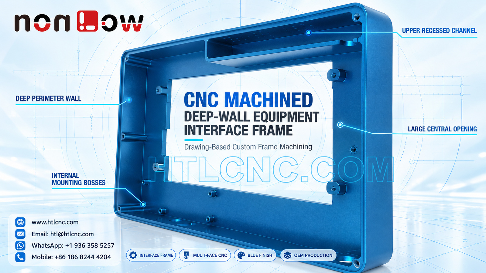
A CNC machined deep-wall equipment interface frame combines a large central opening, tall perimeter walls, internal mounting bosses and an upper recessed channel that must share one assembly datum structure.
A CNC machined deep-wall equipment interface frame surrounds a large rectangular opening with tall perimeter walls, internal mounting bosses, corner fastening locations and a long recessed channel along one interior edge. The selected photograph also shows a blue finish, but it does not prove the finish process, base material, tolerance, certification or final application. HTL CNC supports drawing-based custom frame machining for overseas OEMs, equipment builders, product-development companies, engineers and procurement teams from prototype review through repeat supply.
What Is a Deep-Wall Equipment Interface Frame?
A deep-wall equipment interface frame is a three-dimensional bezel or housing frame whose broad central opening is surrounded by a substantial wall depth. It may locate another panel, display, cover or assembly, but the exact function must come from the released product documentation rather than visual appearance.
For quotation, send the controlled 2D drawing, STEP file, mating-part models, exact material and condition, prototype and production quantities, annual demand, critical tolerances, finish, inspection-document scope, packaging, destination and delivery target. Mark the functional seating faces, cosmetic zones and areas that may accept workholding evidence.
Establish Datums from the Real Assembly
The large opening and perimeter create several convenient surfaces, but the easiest surface to probe is not necessarily the correct assembly datum. The drawing should identify the face that seats the frame, the feature that controls lateral position and the feature that fixes rotation.
A functional datum scheme lets the supplier relate the central opening, internal bosses, upper recess and corner fastening points to one coordinate system. HTL's custom CNC machining service reviews the drawing and mating geometry before workholding and inspection methods are released.
Control the Large Central Opening as a Complete Profile
The central opening dominates the visible geometry. Its width and height alone do not define fit. The drawing may also need corner radii, edge profile, wall position, local notches and profile tolerance relative to the assembly datums.
If a panel, screen, cover or other component enters the opening, provide its actual model and the required clearance or overlap. The photograph cannot establish whether the edge supports bonding, a gasket, a clip or another interface. Those details should remain explicit in the product definition.
Protect Deep Perimeter Walls from Distortion
Tall walls can respond to clamp force and material removal differently from a flat plate. Process planning should consider starting stock, wall thickness, unsupported spans, roughing balance, support locations and the sequence used to finish the seating face, wall profile and opening.
Flatness, straightness, perpendicularity and profile solve different risks. Buyers should assign only the controls needed for assembly and define whether inspection is performed free, supported or fastened. A fixture that forces the frame into shape can hide distortion that returns after release.
Treat Internal Mounting Bosses as an Assembly Pattern
Several internal bosses and threaded locations are visible around the opening. Their height, thread axis, position and relationship to the seating face can affect a mating panel or internal component. The released drawing should define thread form, depth, entry treatment, minimum full thread and any insert requirement.
The bosses should be inspected as a coordinated pattern when they locate one part. Thread gauges verify thread form but not group position. Coordinate measurement or a customer-approved functional fixture can confirm that the boss pattern and central opening remain aligned.
Define the Upper Recessed Channel Separately
A long recessed channel is visible along the upper interior region. Its function is not proven by appearance. The drawing should define its width, depth, end geometry, floor position and relationship to the central opening and side walls. Any mating insert, label, light guide, seal or other component should be supplied only when relevant to the actual assembly.
The channel may require tool reach close to the perimeter wall. Cutter diameter, stick-out and chip evacuation should be reviewed against the complete model. A generic pocket note may be insufficient when the end conditions or local clearance are functional.
Plan Multi-Face Machining Around Transfer Datums
The deep frame includes internal, edge and side features that may require more than one orientation. Depending on tolerance, quantity and access, production can use qualified 3-axis refixturing, indexed workholding, 5-axis CNC machining or another controlled route.
The objective is not the highest axis count. It is to reduce uncertain datum transfers while keeping the walls stable and leaving measurement access. Prototype fixtures may prioritize flexibility; recurring orders may justify a dedicated nest located from approved functional surfaces.
Keep Finish Requirements Evidence-Based
The blue appearance proves only that the photographed part has a blue surface. It does not identify anodizing, paint, coating chemistry or the substrate. Purchase documents should state the exact finish process, pretreatment, color standard, gloss or texture target, coating allowance, masking, cosmetic zones and certification scope.
The broad rim, deep walls and recessed regions can reflect light differently. If appearance is important, define the viewing conditions and an approved limit sample. Threads, boss faces and locating edges may require masking or post-finish inspection.
Inspect Relationships, Not Only Individual Dimensions
A risk-based first-article report may include the primary seating plane, outside envelope, central-opening profile, deep-wall geometry, boss pattern, threaded features, upper-channel dimensions, corner fastening locations and drawing-defined geometric tolerances. The report should identify the revision, datum setup, finish condition and inspection restraint.
Measurement may combine CMM probing, height systems, thread and pin gauges, optical equipment and customer-approved functional masters. Individual sizes are useful, but the buyer also needs evidence that the window, bosses, recess and seating surfaces remain coordinated.
Validate the Prototype with the Mating Assembly
Prototype quantities allow engineering teams to check panel fit, boss alignment, fastener access, upper-channel clearance, side-feature access and cosmetic acceptance. Sealing, impact, environmental, optical or life performance requires customer-defined tests and acceptance criteria; none should be inferred from a photograph.
HTL's prototype and low-volume CNC machining service supports samples and pilot lots before dedicated fixtures, sampling plans and packaging are fixed. Approved changes should update the 2D drawing, STEP model, mating files and inspection plan under one controlled revision.
Prepare the Frame for Repeat OEM Production
Repeat supply should lock the approved stock source, fixture identification, CNC program revision, first-piece approval, tool-life rules, finish batch control and sampling frequency. The transfer-datum method and boss-pattern checks should remain in the setup documentation rather than depending on operator memory.
Packaging should protect the finished rim, deep walls, bosses and opening edges from impact or metal-to-metal contact. Formed trays, separators, protective films or individual sleeves may be selected according to the accepted finish and export route. Labels should identify part number, revision, quantity and production lot.
RFQ Checklist for a Deep-Wall Equipment Interface Frame
Provide the released 2D drawing and STEP file, mating-panel and assembly models, exact material and condition, prototype and repeat quantities, annual demand, functional datum structure, central-opening profile, wall requirements, boss and thread callouts, upper-channel definition, side features, geometric controls, finish specification, first-article scope, packaging, destination and target schedule. Confidential files can be reviewed under the buyer's required document-control process.
This package allows HTL CNC to quote the CNC machined deep-wall equipment interface frame as a controlled multi-face manufacturing and inspection program. For a related enclosure-interface topic, see our guide to CNC machined partial-fin equipment enclosure control.
Website: www.htlcnc.com Email: htl@htlcnc.com WhatsApp: +1 936 358 5257 Mobile: +86 186 8244 4204
Have a part ready for engineering review?
Send your drawing, STEP file, material and quantity directly to HTL CNC for a manufacturing quotation.