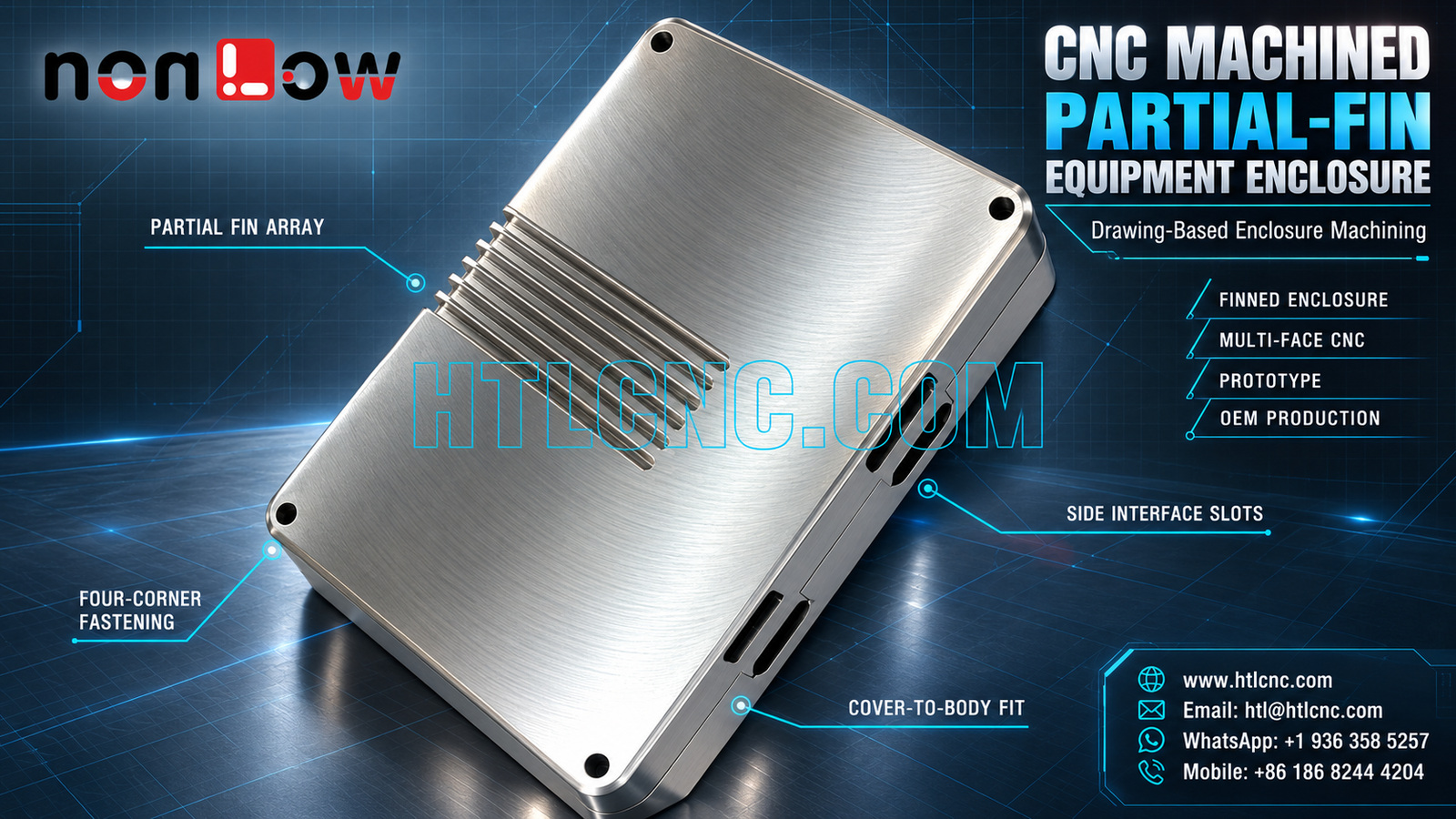
A CNC machined partial-fin equipment enclosure combines a localized external fin array, broad cover surface, four-corner fastening and side slots that require coordinated multi-face machining and inspection.
A CNC machined partial-fin equipment enclosure combines a broad cover surface with a localized parallel-fin array, four corner fastener positions, a visible cover-to-body joint and rectangular openings on the side wall. Those features are directly supported by the selected photograph. The image does not prove the material grade, thermal rating, manufacturing route, sealing level, finish specification or final application. HTL CNC treats the pictured geometry as a drawing-based custom enclosure machining project for overseas OEMs, equipment builders, product-development companies, engineers and procurement teams.
What Is a Partial-Fin Equipment Enclosure?
A partial-fin equipment enclosure is a housing whose exterior combines an unfinned region with a localized field of parallel ribs or fins. The released design may use the different regions for several purposes, but appearance alone does not establish a thermal function. Buyers should identify the functional surfaces, interfaces and any verified performance requirement in the RFQ.
The sourcing package should include a controlled 2D drawing, STEP file, mating-part data, exact material and condition, prototype and production quantities, annual demand, critical tolerances, finish, inspection-document scope, packaging, destination and target delivery. Any thermal, environmental, structural or electrical test must include the customer-approved method and acceptance criteria.
Define the Fin Array as a Controlled Feature Group
The visible parallel-fin field occupies only part of the cover and stops at distinct transitions. The drawing should define fin direction, pitch, width, height, root radius, end profile and the location of the complete array relative to functional datums. A generic note for one typical fin is insufficient when the start and end conditions affect adjacent surfaces.
Fin geometry can restrict cutter access and create narrow spaces for chip retention. Tool selection, step-over and cleaning methods should preserve the specified profile without rolling the fin edges. If the fins are intended to support a validated thermal design, the buyer should supply the approved geometry and test plan rather than asking the supplier to infer performance from the photograph.
Establish the Cover-to-Body Datum Chain
A joint line is visible around the enclosure perimeter. The hidden internal lip, rebate, groove or gasket geometry cannot be confirmed from the exterior view, so the released model must define the actual interface. Identify which face controls seating, which feature controls lateral position and which feature prevents rotation.
Cover flatness, perimeter profile and body-opening geometry can interact during fastening. HTL's custom CNC machining service reviews the full assembly data before selecting workholding and inspection methods. If the enclosure must be evaluated under a specified screw sequence or torque, include those conditions in the drawing or test instruction.
Treat Four Corner Holes as One Fastener Pattern
Four corner holes are visible, but the photograph does not prove whether they are clearance holes, threads, countersinks or counterbores. The drawing should state the complete callout, depth reference, edge distance and positional relationship to the mating interface.
The fasteners should be inspected as a coordinated pattern when they align the cover and body. Individual hole size checks cannot demonstrate assembly interchangeability. Prototype evaluation may combine gauges, coordinate measurement and a customer-approved mating-cover check.
Coordinate Side Slots with the Main Enclosure Datums
Rectangular slots are visible on the side wall. Their function is not established by appearance, so the buyer should define width, length, corner radius, wall position, edge break and any profile or position requirement. Mating connector, switch, vent, cable or other interface models should be provided only when relevant to the actual product.
Side-slot machining introduces a cross-face relationship to the cover and corner pattern. Depending on tolerance, access and quantity, the route may use qualified 3-axis refixturing, indexed workholding, 5-axis CNC machining or another controlled method. The process should minimize uncertain datum transfers rather than select an axis count for marketing reasons.
Protect the Broad Cover Surface During Workholding
The broad exterior includes both a smooth area and the partial fin array. Clamping directly on the visible face can mark the surface or force the joint temporarily flat. A process plan should identify robust locating areas, clamp zones, support points and the inspection state after release.
Flatness, parallelism and profile are different controls. The buyer should apply them only where assembly or appearance requires them and define whether limits apply before or after finishing. If the cover is flexible, free-state inspection and a separate assembled-state check can prevent disagreement.
Separate Machining Texture from the Final Finish Specification
The photograph shows a bright machined appearance, but it does not identify an alloy, temper, coating or final surface treatment. Purchase documents should specify the material standard and condition, heat treatment where applicable, finish process, coating allowance, masking, color or texture target, cosmetic zones and certification requirements.
The smooth cover region and fin field may reflect light differently even when they receive the same treatment. If appearance consistency matters, define the viewing conditions and an approved limit sample. Corner holes, joint faces and side slots may require post-finish dimensional verification.
Build First-Article Inspection Around Interfaces
A risk-based first-article report may include the primary seating plane, overall envelope, cover perimeter, joint profile, four-hole pattern, fin-array position and profile, side-slot location and drawing-defined geometric tolerances. Record the drawing revision, datum setup, finish condition and whether the enclosure was measured free or assembled.
Measurement can combine height systems, depth and pin gauges, optical equipment, CMM probing and customer-approved functional fixtures. Fin pitch and slot size matter, but the report should also prove that the array, fastening pattern and side interfaces remain related to the same assembly datums.
Use Prototypes to Verify Assembly and Performance
Prototype quantities allow the engineering team to check cover seating, screw alignment, side-slot clearance, internal component envelope, tool access and cosmetic acceptance. Thermal, ingress, vibration, electromagnetic or life performance requires customer-defined test equipment and pass criteria; it cannot be validated from a product photograph.
HTL's prototype and low-volume CNC machining service supports engineering samples and pilot lots before dedicated fixtures and recurring inspection plans are released. Approved changes should update the 2D drawing, STEP model, assembly files and inspection plan under one coordinated revision.
Qualify the Supplier for Repeat OEM Orders
Repeat production should control stock source, fixture identification, CNC program revision, first-piece approval, tool-life limits, cleaning and sampling frequency. For a finned equipment enclosure, fin damage, side-slot burrs and cover-interface condition should remain visible in the process documentation rather than depending on operator memory.
Packaging should prevent metal-to-metal contact and protect the fins, cosmetic cover area, corner holes and side openings. Formed trays, separators, films or individual sleeves may be selected according to the approved finish and export route. Labels should identify part number, revision, quantity and production lot.
RFQ Checklist for a CNC Machined Partial-Fin Equipment Enclosure
Send the released 2D drawing and STEP file, cover and body assembly models, exact material and condition, prototype and repeat quantities, annual demand, functional datum scheme, fin-array definition, corner-hole callouts, side-slot profiles, wall thicknesses, tolerances, finish, performance tests, first-article scope, packaging, destination and target schedule. Confidential drawings can be reviewed under the buyer's required document-control process.
This information allows HTL CNC to quote the CNC machined partial-fin equipment enclosure as a controlled multi-face machining and inspection program. For a related internal-geometry topic, review our guide to CNC machined patterned-interior equipment enclosure control.
Website: www.htlcnc.com Email: htl@htlcnc.com WhatsApp: +1 936 358 5257 Mobile: +86 186 8244 4204
Have a part ready for engineering review?
Send your drawing, STEP file, material and quantity directly to HTL CNC for a manufacturing quotation.