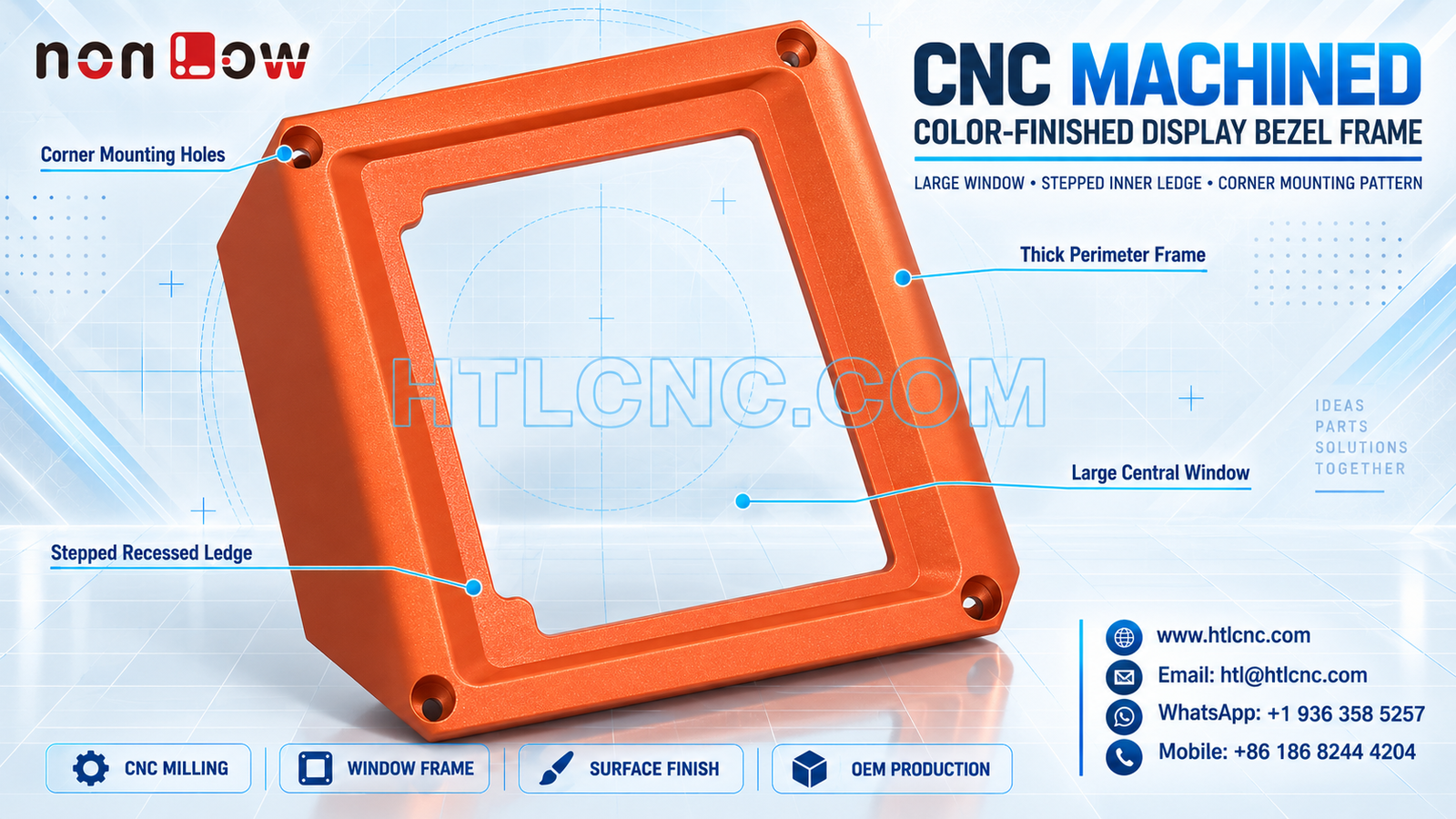
A CNC machined display bezel frame combines a large central window, stepped inner ledge, thick perimeter walls and four corner mounting features that must remain coordinated through machining, finishing and inspection.
A CNC machined display bezel frame is more than a cosmetic border around a large opening. The selected photographs visibly show one orange color-finished frame with a broad central window, a continuous stepped inner ledge, thick perimeter walls, clipped outer corner zones, four corner mounting features and small asymmetric reliefs along the inner edge. The images do not prove the material grade, exact coating process, dimensional tolerances, sealing function or final equipment. Those requirements must come from the buyer's released drawing, STEP model and assembly specification. HTL CNC supports overseas OEMs, product-development teams, equipment builders, engineers and procurement professionals with drawing-based custom CNC machining, prototypes, low-volume production and repeat supply.
Qualify the Supplier Around the Display Interface
The primary sourcing question is whether the frame will locate and protect the customer's actual window, display, lens, membrane or another mating component. These are possible interface examples, not verified uses of the pictured part. The RFQ should identify the primary mounting face, the opening centerlines, the surface that supports the insert and the feature that prevents rotation or lateral movement.
Mating-part data helps the supplier separate functional geometry from visual styling. HTL's custom CNC machining service can review the controlled 2D drawing, STEP file and interface model before the machining and inspection route is released.
Treat the Large Window as a Profile, Not Just Length and Width
The visible opening includes rounded corners and local relief features that are not represented by two overall dimensions alone. The drawing should define the complete profile, corner radii, edge breaks, permitted cutter relief and relationship to the external frame. If a gasket, lens or display sits inside the opening, its maximum material boundary and required assembly clearance should be included.
Profile tolerancing may provide a clearer requirement than long chains of coordinates when the full opening must align with one mating component. A first article can be checked with CMM or optical measurement and then confirmed with the real insert or an approved functional gauge.
Control the Stepped Inner Ledge as a Seating Surface
A continuous recessed ledge is visible around the central window. Its width, depth, flatness and relationship to the front face may influence seating, adhesive thickness, gasket compression or simple clearance, but the photograph does not establish which function applies. The released drawing should state the required condition without relying on appearance.
Workholding and tool paths should keep this ledge stable while the surrounding material is removed. If the ledge is interrupted by reliefs, those transitions should be dimensioned so the supplier does not blend or sharpen them according to personal preference.
Keep the Four Corner Mounting Features in One Pattern
The frame visibly contains one mounting feature near each corner, with counterbored or recessed geometry apparent in the photographs. Hole size alone is not enough when assembly depends on the complete pattern. Basic coordinates, position tolerance, counterbore diameter and depth, fastener-head clearance and any thread requirement should be specified from the functional datums.
The drawing should also distinguish locating holes from clearance holes. If one feature establishes location and the others allow assembly variation, that intent should be explicit so inspection does not apply the same acceptance logic to every corner.
Plan Workholding Around a Large Open Structure
Removing the central window leaves a broad but interrupted perimeter frame. Clamping force and cutting sequence can influence free-state flatness, especially when the frame has different wall widths or local reliefs. A fixture should support stable regions without loading the stepped ledge or obstructing through-features.
A balanced roughing strategy can leave temporary support before critical surfaces are finished. The exact process depends on stock condition, material, frame depth, tolerance and production quantity. Buyers should therefore avoid requiring a fixed machine setup before the supplier reviews the complete model.
Separate Dimensional Acceptance from Cosmetic Acceptance
The orange appearance confirms a color-finished surface, but it does not prove anodizing, powder coating, paint or another treatment. The RFQ should provide the exact material and finish specification, approved color reference, gloss or texture expectation, coating thickness where applicable, masking zones and permitted cosmetic defects.
Critical seating faces, mounting recesses and fit boundaries may need protection from coating buildup. The drawing should state whether dimensions apply before or after finishing. A signed color and texture sample can support appearance control, while dimensional inspection remains tied to the released drawing.
Protect Edges and Broad Cosmetic Faces During Production
A display bezel frame often presents large visible surfaces around the opening. Even when appearance is important, the photograph alone cannot define which face is customer-visible. The drawing should mark Class A or equivalent cosmetic zones, acceptable tool marks, scratch limits and edge-break requirements.
Handling trays, soft separators and protective film may be required between machining, finishing, inspection and export packaging. The supplier should also control fixture contact marks so a dimensionally conforming part is not rejected after surface treatment.
Build First-Article Inspection Around Assembly Risk
A risk-based first-article report may include the outer profile, overall thickness, mounting-face flatness, central-window profile, ledge width and depth, corner-hole size and position, counterbore geometry, local reliefs and drawing-defined geometric tolerances. Results should reference the approved revision and the actual datum setup used.
CMM inspection, optical systems, height measurement, pin or bore gauges and a functional checking fixture may be combined according to tolerance and feature access. Overseas buyers should state whether they require selected critical dimensions, a full first-article report, material certificates, finishing records or lot-level inspection data.
Validate the Prototype with the Mating Assembly
Prototype approval should include fit through the central window, seating on the inner ledge, corner-pattern alignment, fastener-head clearance, front-surface appearance and access for the intended assembly method. Any adjustment to reliefs, radii or coating allowance should update the 2D drawing and STEP file under the same controlled revision.
HTL's prototype and low-volume CNC machining service supports engineering samples and staged pilot quantities. After approval, locked programs, qualified fixtures, finish samples, first-piece checks and revision control help transfer the frame into repeat OEM production.
Prepare a Complete RFQ for Repeat Supply
Send the released 2D drawing and STEP file, mating-display or insert data, exact material, prototype and production quantities, annual demand, datum scheme, window-profile requirements, ledge dimensions, mounting-pattern tolerances, corner-hole details, surface-finish specification, cosmetic criteria, inspection documents, packaging, destination and delivery target. Confidential drawings can be handled under the buyer's required document-control process.
This package allows HTL CNC to quote the CNC machined display bezel frame as a controlled manufacturing program rather than guessing from a photograph. Related teams sourcing broad framed components may also review our guidance on precision CNC recessed-frame control.
Website: www.htlcnc.com Email: htl@htlcnc.com WhatsApp: +1 936 358 5257 Mobile: +86 186 8244 4204
Have a part ready for engineering review?
Send your drawing, STEP file, material and quantity directly to HTL CNC for a manufacturing quotation.