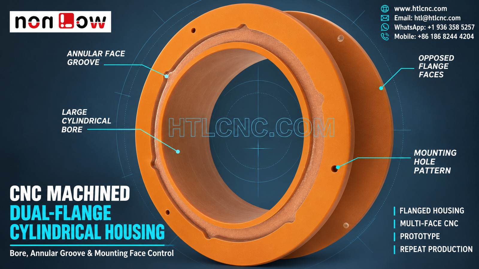
A CNC machined dual-flange cylindrical housing combines a large through bore, opposed mounting faces, an annular groove and flange-hole patterns that require one coherent datum and inspection strategy.
A CNC machined dual-flange cylindrical housing combines a large through bore, a cylindrical wall, opposed flange faces, an annular face groove and distributed mounting holes in one integrated component. The selected photograph clearly shows those features on an orange-brown housing, but it does not establish the material, groove function, sealing requirement, tolerance, load or final equipment. HTL CNC supports drawing-based custom CNC machining for overseas OEMs, equipment builders, product-development companies and procurement teams from prototype qualification through repeat production.
Begin Supplier Review with the Mating Stack
The buyer should identify what passes through or locates in the bore, what contacts each flange face, which holes fasten the housing and whether the annular groove carries a seal, retainer or another feature. Simplified mating envelopes allow the supplier to understand the functional stack without requiring unrelated system disclosure.
A complete RFQ includes the released 2D drawing, STEP model, exact material and condition, prototype and production quantities, annual demand, finish, tolerances, inspection-document scope, packaging and destination. HTL's custom CNC machining service reviews those inputs before stock, fixture and measurement planning.
Establish the Bore Axis as a Functional Reference
The large cylindrical bore is the central geometric feature. If it locates a mating component, the drawing should define diameter, roundness or cylindricity as required, surface condition, edge breaks and the relationship of the bore axis to both flange faces.
A bore can meet diameter while its axis is tilted or offset relative to the mounting interfaces. Inspection may use bore gauges, CMM probing, rotary measurement or a customer-approved master according to the tolerance and component size. The report should identify the measured length and datum setup.
Control Opposed Flange Faces as One Axial Stack
The visible component has flange faces on opposite ends of the cylindrical wall. Their spacing, flatness and relationship to the bore axis may govern assembly. The drawing should state which face is primary, how the opposite face is located and whether face parallelism, perpendicularity or axial runout applies.
If the faces are machined in separate setups, a stable process must preserve the axial datum. Soft jaws, a dedicated nest, an expanding fixture or another drawing-based solution may be evaluated from the real geometry and material.
Define the Annular Groove as a Complete Path
An irregular annular groove is visible around the front opening. The image does not prove whether it is a gasket groove, retaining path, relief or another interface. The released drawing should specify its complete route, width, depth, local notches, corner radii, surface condition and positional relationship to the bore and mounting face.
Checking only a few straight sections cannot confirm the entire feature. Selected depth and width measurements can be combined with CMM or optical profile data. If sealing performance matters, the customer must provide the mating hardware, compression method, test condition and pass criteria; dimensional results alone do not certify leakage performance.
Coordinate Mounting-Hole Patterns on Both Flanges
Several holes are visible around the flange perimeters. Their exact function and thread condition cannot be confirmed from the photograph. A hole schedule should identify size, depth, thread or clearance requirement, countersink or counterbore details, positional tolerance and final gauge method.
Patterns on opposite faces should share a clear clocking reference when the housing connects two assemblies. Prototype inspection can compare pattern center, angular spacing and hole location relative to the bore axis rather than treating each hole independently.
Select the Machining Route from Material and Quantity
The orange-brown appearance does not identify the substrate. The buyer must specify the exact material, condition, approved stock form and any directional or handling requirements. Different materials can require very different cutting tools, speeds, dust or chip controls, fixturing and inspection methods.
Depending on the released geometry, a qualified route may combine turning for the bore and circular faces with milling or drilling for flange patterns and groove details. HTL's CNC turning and turn-mill machining service can review axis continuity, reversal strategy and cross-face access from the complete model.
Manage Large-Diameter Stability and Clamping
Broad flanges can respond to uneven clamp force or material removal. Workholding should support stable regions without masking the groove or forcing a temporarily flat condition. The inspection specification should state whether face flatness and spacing are checked free-state, on defined supports or under assembly restraint.
First-piece qualification can record support points, fixture revision, clamping sequence and results after release. This helps distinguish actual machining error from temporary fixture deformation.
Separate Surface Appearance from Finish Requirements
The source image shows a colored surface, but appearance alone does not establish coating, laminate, molding condition or post-machining treatment. The purchase order should define material documentation, finish standard, protected faces, cosmetic acceptance, masking, certificates and any post-process dimensional checks.
Bore surfaces, flange lands, groove edges and holes may need different requirements. Packaging material should be compatible with the actual surface and should not leave residue on functional faces.
Build First-Article Inspection around Datum Relationships
A useful first-article report can cover the primary flange face, bore size and axis, opposite-face spacing, face relationship, annular groove profile, flange-hole patterns, outer envelope and drawing-defined geometric tolerances. It should identify revision, datum setup, free or restrained condition, measurement equipment and gauge IDs.
A related guide to flanged cylindrical housing CNC machining covers additional bore, flange and OEM assembly considerations for similar rotational housings.
Validate the Prototype with Both Mating Interfaces
Prototype approval should use the actual upstream and downstream interfaces or customer-approved masters. The engineering team can check bore clearance, flange seating, angular clocking, fastener access, groove engagement and assembly sequence before production tooling and sampling plans are fixed.
HTL's prototype and low-volume CNC machining service supports engineering samples and pilot lots. Approved corrections should update the 2D drawing and STEP model under one controlled revision so machining, inspection and purchasing follow the same definition.
Move the Approved Housing into Repeat OEM Production
Repeat supply depends on controlled material, CNC program revision, fixture identification, tool-life rules, first-piece approval, calibrated gauges and formal change management. Annual demand and batch size should be shared early because they affect stock planning, fixture investment, inspection capacity and delivery cadence.
Export packaging should support the housing without loading the flange edges or groove. Nonabrasive separators, formed supports or individual sleeves can prevent contact between functional surfaces. Labels should link part number, revision, quantity and lot to the inspection record.
RFQ Checklist for a Dual-Flange Cylindrical Housing
Send the released 2D drawing and STEP file, mating-interface information, exact material and condition, approved stock form, prototype and production quantities, annual demand, bore and datum requirements, opposed flange-face relationship, annular groove definition, complete hole schedule, tolerances, finish, inspection documents, packaging, destination and delivery target. Confidential files can be reviewed under the buyer's required document-control process.
This information allows HTL CNC to quote the CNC machined dual-flange cylindrical housing as a controlled machining and inspection program rather than estimating material or function from a photograph. For engineering review and quotation, visit www.htlcnc.com, email htl@htlcnc.com, send WhatsApp to +1 936 358 5257, or call mobile +86 186 8244 4204.
Have a part ready for engineering review?
Send your drawing, STEP file, material and quantity directly to HTL CNC for a manufacturing quotation.