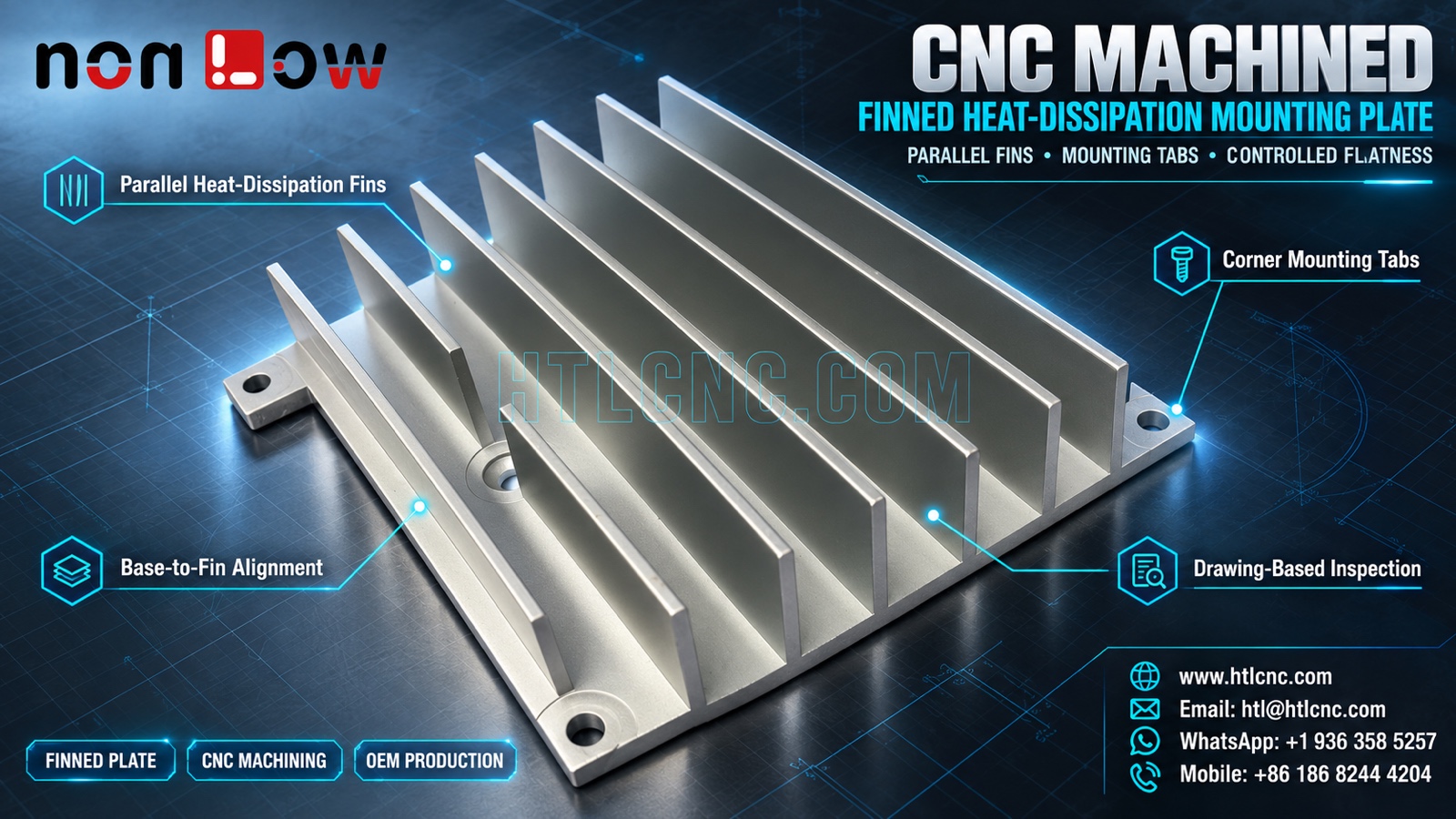
A CNC machined finned heat-dissipation mounting plate combines a broad base, parallel fins, perimeter mounting tabs and local recessed holes that must remain coordinated through drawing review and inspection.
A CNC machined finned heat-dissipation mounting plate gives equipment builders one component for mechanical attachment and a customer-defined thermal interface. The selected photograph visibly shows a rectangular metallic base with a repeated array of tall parallel fins, projecting perimeter tabs with mounting holes and local circular recessed features between the fins. The image does not identify material grade, stock-making route, exact tolerances, coating, heat source, airflow direction or thermal rating. HTL CNC supplies drawing-based custom components for overseas OEMs, product-development teams, equipment manufacturers, engineers and procurement groups from prototype review through repeat production.
Treat Thermal Performance as a Customer-Defined Requirement
Fins increase exposed surface area, but a photograph cannot establish heat flow, operating temperature or required thermal resistance. The buyer should provide the heat-source location, interface area, power range, duty cycle, airflow condition, orientation and validation method. Thermal analysis and system testing remain part of the customer's approved design process.
The machining supplier's responsibility is to manufacture the drawing-defined geometry and provide agreed inspection evidence. The RFQ should separate dimensional requirements from product-level thermal acceptance so both parties understand which tests belong to each scope.
Select the Manufacturing Route from the Complete Geometry
The visible part may begin as an extruded, cast or machined blank, but the image does not prove which. Fin thickness, fin height, spacing, base thickness, cross-section consistency, quantity and material specification determine whether a near-net profile plus secondary CNC machining or a more fully machined route is appropriate.
HTL's custom CNC machining service reviews the 2D drawing, STEP model, annual demand and inspection scope before recommending a process. Machine selection should follow feature access and datum relationships rather than treating every finned part as the same manufacturing problem.
Define Fin Geometry Beyond Height and Pitch
A useful drawing identifies fin count, thickness, height, pitch, length, root radius, tip condition, allowable bow and any local interruptions. The repeated fins should be controlled as a coordinated array because a single fin can meet thickness while the full pattern drifts across the base.
Fin roots and narrow channels can restrict cutter access, chip evacuation and inspection. If the fins come from a near-net profile, secondary machining must protect them from clamp damage. If they are milled from solid stock, tool reach, chatter, heat generation and remaining-wall stability become important process-review topics.
Protect the Base-to-Fin Relationship
The base carries the fin array and appears to include local pads or recessed holes. The drawing should identify the primary seating plane and specify which surface forms the thermal-contact interface. Fin perpendicularity, base flatness and the relationship between the two may matter more than the cosmetic appearance of individual surfaces.
Clamping across a wide base can temporarily flatten a bowed blank or distort thin regions. Inspection should therefore state whether flatness applies in a free state or under a defined assembly load. A qualified fixture can support the base near stable zones while leaving the functional contact surface available for final machining and measurement.
Control Mounting Tabs as an Assembly Pattern
Projecting tabs with holes are visible around the perimeter. Their exact function, fastener type and clearance cannot be confirmed from the image. The drawing should define tab thickness, outside profile, hole diameter, counterbore or countersink details, edge distance and position relative to the primary seating plane and selected coordinate datums.
A group of individually acceptable holes can still fail installation when the complete pattern is shifted or rotated. First-article inspection should verify pattern position and, where appropriate, use a customer-approved mating plate or gauge to confirm assembly without forcing the base.
Specify Local Recessed Features Between the Fins
Circular recessed features appear in the base between selected fins. The source does not prove whether they are mounting seats, clearance holes, locating features or another interface. Each one should be numbered and defined by diameter, depth, bottom condition, through-hole size, edge break and coordinate position.
Access between tall fins can limit tool diameter, spindle clearance and probe approach. The process plan may establish local features before the fin geometry is vulnerable, or use extended tooling and dedicated inspection methods after the profile is complete. The released model and tolerance stack determine the safer sequence.
Manage Deburring and Cleaning in Narrow Fin Channels
Long channels can retain chips, cutting fluid or finishing media. The purchase specification should define cleanliness, prohibited residue and any handling requirement for sharp fin tips. Deburring must remove loose material without thinning a fin, rounding a drawing-controlled tip or changing the root transition.
Cleaning and visual inspection should cover the full channel length, fin roots, recessed holes and mounting tabs. If the component enters an electronics or optical assembly, the customer should state particle, oil or packaging limits rather than relying on a generic clean-part note.
Finish Selection Must Follow Material and Interface Needs
The metallic appearance does not prove aluminum, anodizing or another treatment. The RFQ should identify material standard and condition, surface finish, corrosion requirements, cosmetic zones and certificate scope. Any coating allowance or masking requirement should be defined for mounting holes, thermal-contact surfaces and close-fitting recesses.
A finish can change contact behavior, hole size and flatness measurement. Critical interface dimensions should state whether they apply before or after finishing. Protected packaging may be needed to keep fins separated from adjacent parts and prevent abrasion during export shipment.
Build a First-Article Plan Around Functional Relationships
A risk-based report can cover overall envelope, base thickness and flatness, fin count and pitch, representative fin height and thickness, fin perpendicularity, local recessed features, perimeter mounting pattern and drawing-defined geometric tolerances. The report should identify part revision, datum setup, measurement method and free or restrained condition.
Measurement may combine height systems, micrometers, pin and depth gauges, optical equipment, CMM probing and functional fixtures. Deep channels may require planned probe access or approved sampling positions. Supplier qualification should agree the report format before production, not after the first lot is complete.
Validate the Plate in a Prototype Assembly
Prototype quantities let the engineering team verify mounting-hole alignment, base seating, contact-area coverage, fastener access, adjacent-component clearance and fin orientation in the real assembly. Thermal testing requires the customer's defined heat load, interface material, airflow and pass criteria; dimensional inspection alone cannot demonstrate system cooling performance.
HTL's prototype and low-volume CNC machining service supports engineering samples and pilot lots before recurring production controls are locked. Approved design changes should update the drawing, STEP file, thermal interface definition and inspection plan under one revision.
Transfer the Approved Route into Repeat OEM Production
After prototype approval, consistent supply depends on controlled blank specifications, CNC programs, fixture identification, first-piece approval, tool-life rules, inspection sampling and formal revision management. Changes to fin geometry, stock source, contact-face machining or finish should trigger a defined review because they can affect both dimensions and the customer's thermal validation.
Export packaging should support the base without loading fin tips. Individual trays, separators or formed supports can protect the fin array and mounting tabs. Labels should identify part number, revision, lot and quantity so receiving inspection can trace the shipment to the correct records.
RFQ Checklist for a Finned Heat-Dissipation Mounting Plate
Send the released 2D drawing and STEP file, assembly model, exact material and condition, permitted stock route, prototype and production quantities, annual demand, heat-source and contact-surface definition, fin geometry, mounting-tab and hole requirements, recessed-feature schedule, tolerances, flatness condition, surface finish, cleanliness, inspection-document scope, packaging, destination and target schedule. Confidential technical files can be reviewed under the buyer's required document-control process.
This information allows HTL CNC to quote the CNC machined finned heat-dissipation mounting plate as a controlled manufacturing and inspection program rather than estimating performance from a photograph. For a related geometry example, review our article on integrated finned CNC mounting frame datum control.
Website: www.htlcnc.com Email: htl@htlcnc.com WhatsApp: +1 936 358 5257 Mobile: +86 186 8244 4204
Have a part ready for engineering review?
Send your drawing, STEP file, material and quantity directly to HTL CNC for a manufacturing quotation.