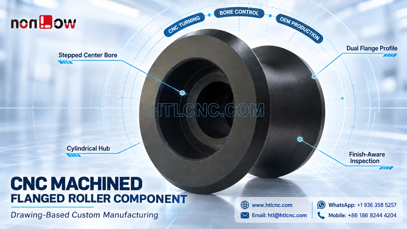
A CNC machined flanged roller component combines a stepped center bore, broad front flange, rear flange profile and cylindrical hub that require one coordinated turning and inspection strategy.
A CNC machined flanged roller component is a rotationally symmetric part whose visible features must remain coordinated around one center axis. The selected photograph shows one dark-finished component with a broad front flange, a smaller rear flange, a cylindrical middle body and multiple concentric steps around a central bore. These features support a flanged-roller manufacturing topic, but the photograph does not establish material, bearing arrangement, mating shaft, load, speed, tolerance, coating chemistry or final equipment. HTL CNC provides drawing-based CNC turning and custom machining for overseas OEMs, product-development companies, equipment builders, engineers and procurement teams from prototype sourcing through repeat production.
Define the Functional Rotation Stack Before Supplier Quotation
A complete RFQ should identify which diameter locates the component, which faces control axial position, whether the bore receives a shaft, bearing or sleeve, and whether the outer profile contacts another part. Without this information, a supplier can reproduce visible shapes while missing the interfaces that govern assembly.
Send the released 2D drawing, STEP file, mating-component data, exact material and condition, prototype and production quantities, annual demand, tolerances, finish, inspection-document scope and delivery destination. If the component rotates in service, add the customer-defined load, speed, runout limit, lubrication condition and validation method. Those operating requirements cannot be derived from a photograph.
Build One Datum Spine Through the Stepped Bore
The center opening visibly contains more than one diameter and shoulder. Each step should be identified by diameter, axial depth, transition radius or chamfer, surface condition and relationship to the selected datum axis. A bore size alone does not control the alignment of all internal seats.
Where a bearing, bushing or shaft is involved, the buyer should define fit class, mating-part tolerance and inspection temperature. The drawing should also state whether dimensions apply before or after surface treatment. Depending on access and tolerance, measurement may use bore gauges, air gauges, CMM probing, depth tools or customer-approved masters.
Control Front and Rear Flanges as One Profile
The visible component has a large front flange and a smaller rear flange joined by a cylindrical section. Their outside diameters, face positions, thicknesses, edge breaks and profile transitions should reference the same axial system. Treating each flange as an independent turned diameter can leave total width or axial spacing out of control.
Face runout and flange perpendicularity may influence assembly even when outside diameters meet size limits. The released drawing should identify which face is the primary axial datum and whether another face acts as a spacer, guide or retention surface. Cosmetic flatness should not replace drawing-defined geometric control.
Select a Turning Sequence That Preserves Concentric Relationships
Rotational geometry often favors CNC turning, but process selection still depends on stock form, material, tolerance, quantity and complete backside access. A first operation may establish the bore and primary face; a controlled second operation can finish the opposite face and rear profile from qualified locating surfaces.
HTL's CNC turning and turn-mill machining service reviews chucking strategy, jaw contact, datum transfer and inspection access before production. A single setup is useful only when it actually protects the required relationships. For some parts, carefully controlled secondary workholding is more stable than an excessively long or weak first setup.
Separate Bore Concentricity from Outer-Profile Runout
Concentricity, coaxiality and runout are related but not interchangeable. The buyer should specify the characteristic that matches the assembly: bore axis to flange diameter, bore axis to cylindrical hub, face runout to bore axis, or total indicated runout on a functional contact surface.
The inspection plan should name the datum, measurement location, rotation method and acceptance value. A dial indicator on a shop mandrel may support process checks, while first-article reporting may require a CMM, roundness instrument or calibrated functional arbor. Supplier and customer should agree the method before samples are released.
Account for Wall Stability Around the Bore Steps
Deep internal steps can leave local thin sections between the bore and outer hub. The photograph does not reveal complete wall thickness or the backside geometry. The STEP model should therefore be reviewed for minimum wall, tool reach, shoulder access, chip evacuation and potential distortion during chucking.
Roughing stock can be balanced before final bore and face cuts. If clamping pressure temporarily changes roundness, soft-jaw geometry and clamp force should be controlled. Free-state measurement after unclamping is important unless the drawing defines another inspection condition.
Finish Specifications Must Protect Fits and Datums
The dark appearance does not prove the substrate or finish. The purchase order should state material standard, condition, heat treatment, coating or conversion process, color and texture, thickness allowance, masking zones, corrosion requirement, cosmetic areas and certificate scope.
Bore seats, locating faces and close-fit diameters may need masking or a defined post-finish size. If a coating changes friction or thickness, the buyer should confirm whether the mating design and gauge dimensions include that buildup. Handling marks and rack-contact locations should be covered by an approved appearance standard rather than judged from marketing photographs.
Deburr Internal Shoulders Without Changing the Fit
The stepped bore contains internal edges that may be difficult to see or reach. Burrs can interfere with a shaft, sleeve or bearing even when measured diameters are correct. At the same time, excessive hand finishing can round a locating shoulder or enlarge a controlled entrance.
The drawing should identify required edge breaks and any edge that must remain functionally sharp. Cleaning instructions should cover chips, cutting fluid and finishing residue trapped behind bore steps. Where direct inspection is limited, borescope review, controlled flushing or another customer-approved method can be added.
Use Prototype Lots to Validate the Mating Stack
Prototype quantities should be checked with the intended mating components. The customer's engineering team can verify insertion, axial seating, flange clearance, free rotation where applicable, adjacent-part spacing and tool access. Any load, speed, wear, noise or temperature test requires customer-defined fixtures and pass criteria.
HTL's prototype and low-volume CNC machining service supports sample and pilot-lot evaluation before dedicated fixtures and sampling plans are fixed. Approved changes to bore steps, flange spacing, material or finish should update the 2D drawing, STEP model and inspection plan under the same revision.
Qualify Repeat Production with Traceable Process Controls
Repeat supply depends on controlled material lots, chuck and soft-jaw identification, CNC program revision, first-piece approval, tool-life limits, in-process bore checks and final inspection sampling. The same datum path used on the accepted prototype should remain visible in setup instructions and reports.
Packaging should prevent flange faces and finished diameters from contacting neighboring parts. Individual separators, formed trays, bore protectors or clean sleeves may be selected according to finish sensitivity and shipping route. Lot labels should identify part number, revision, quantity and traceability data required at receiving.
RFQ Checklist for a CNC Machined Flanged Roller Component
Provide the released drawing and STEP file, mating shaft, sleeve or bearing data, exact material and condition, prototype and production quantities, annual demand, functional datum axis, complete bore-step schedule, flange diameters and spacing, runout requirements, surface finish, coating and masking details, deburring and cleanliness standard, first-article documentation, packaging, destination and target delivery. Confidential files can be reviewed under the buyer's required document-control process.
A complete package allows HTL CNC to quote the CNC machined flanged roller component as a controlled turning, finishing and inspection program rather than guessing fit or operating performance from appearance. For another rotational geometry, review our guide to multi-groove pulley wheel bore and profile control.
Website: www.htlcnc.com Email: htl@htlcnc.com WhatsApp: +1 936 358 5257 Mobile: +86 186 8244 4204
Have a part ready for engineering review?
Send your drawing, STEP file, material and quantity directly to HTL CNC for a manufacturing quotation.