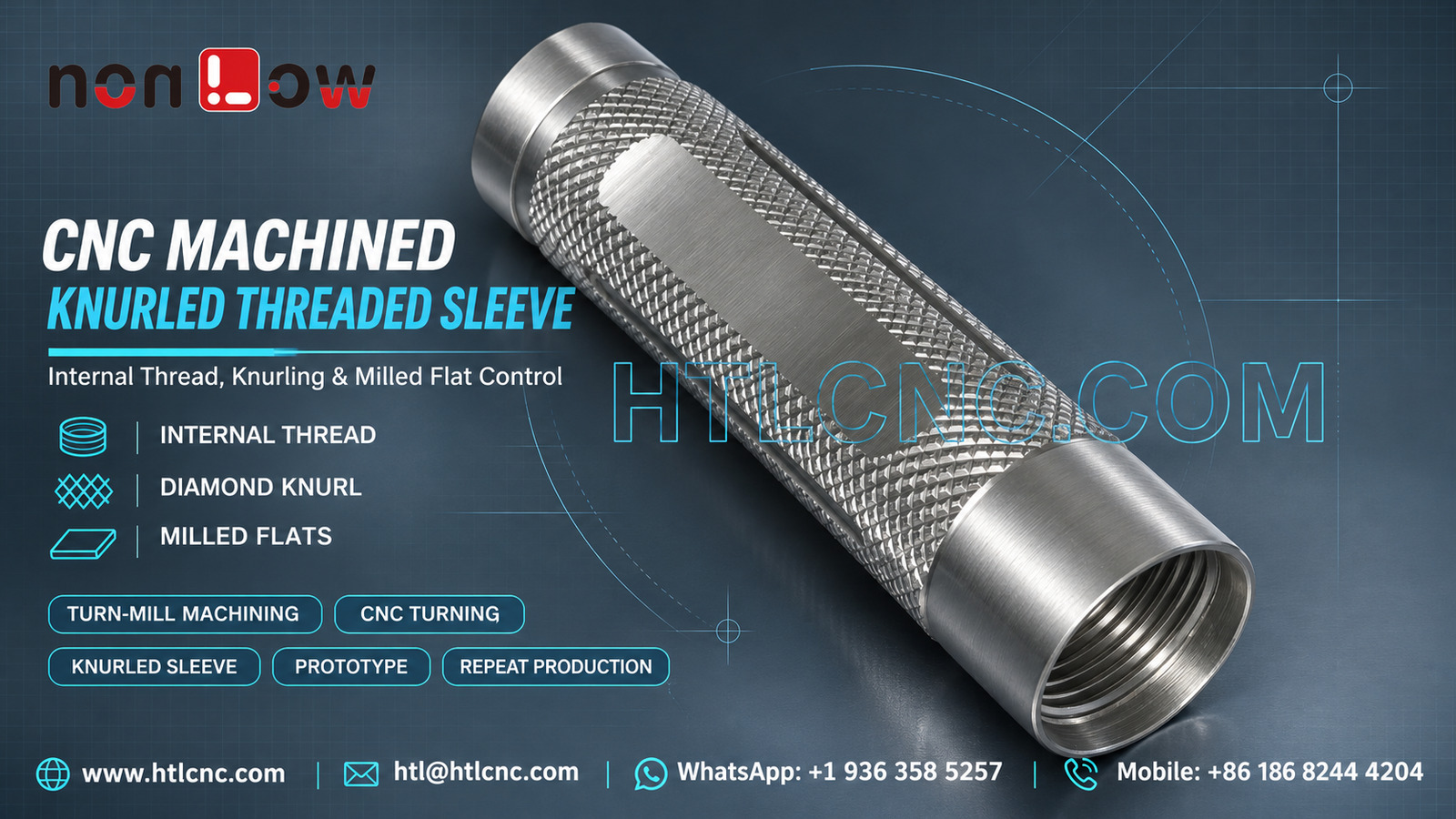
A CNC machined knurled threaded sleeve combines an internal thread, diamond-knurled grip surface, longitudinal milled flats and turned end diameters that require coordinated turn-mill planning and inspection.
A CNC machined knurled threaded sleeve combines a cylindrical body, one visible internal thread, a broad diamond-knurled grip region, longitudinal milled flats and turned end diameters in a compact rotational component. The photograph supports those geometric facts, but it does not establish the material, thread standard, tolerance, load, mating hardware or final application. HTL CNC provides drawing-based CNC turning and turn-mill machining for overseas OEMs, engineering teams and procurement organizations from prototype validation through repeat production.
Start Supplier Qualification with the Threaded Interface
The buyer should identify what engages the internal thread, how far it must enter, what face controls axial seating and whether the opposite end has a drawing-defined bore, slot or closed condition. A simplified mating model can reveal the functional stack without exposing unrelated system details.
A complete RFQ should include the released 2D drawing, STEP model, exact material and condition, full thread callout, prototype and production quantities, annual demand, finish, inspection documents, packaging and destination. HTL's CNC turning and turn-mill machining service reviews those inputs before selecting stock, tooling and setup strategy.
Define the Internal Thread beyond Nominal Diameter
The visible end clearly contains an internal thread, but an image cannot identify its form, nominal size, pitch, class, handedness, lead, usable engagement length or bottom condition. The purchase drawing must state the complete thread specification, entry chamfer, relief, minimum full-thread length and approved gauge method.
A GO/NO-GO gauge can confirm fit limits, but it does not prove that the thread axis is aligned with the sleeve body or that the seating face is correctly located. Where assembly depends on coaxiality or runout, the first-article plan should verify the thread-related axis using a customer-approved mandrel, functional master or another agreed method.
Coordinate Turned Diameters and End Faces
Both ends contain smooth turned regions adjoining the knurled body. Their diameters, shoulders and face locations may establish axial location or support a mating component. The drawing should identify the primary datum face and define the relationships between the cylindrical body, internal thread and opposite-end features.
A turn-mill route may establish the principal rotational geometry before milling the flats. If the component is reversed, soft jaws, a threaded arbor, collet or another qualified workholding method may be evaluated from the actual tolerances and material. Clamp marks on the finished knurl or controlled diameters should be prevented.
Specify the Diamond Knurl as Functional Geometry
The broad exterior grip area has a diamond-cross pattern. Knurling requirements should state the process or finished pattern expected, pitch or tooth count where applicable, major diameter, acceptable crest condition, start and stop boundaries, cosmetic standard and whether partial teeth are permitted near adjacent features.
Knurling displaces or cuts material depending on the specified process. The supplier must review how the operation affects finished diameter, local stress, burrs and neighboring smooth surfaces. A visual sample can supplement the drawing for appearance, but it should not replace dimensional and pattern requirements.
Relate the Longitudinal Flats to the Body Axis
Several long milled flats interrupt the knurled region. They may provide wrench access, orientation or another assembly interface, but their purpose cannot be assumed. The drawing should define flat width, depth or across-flat dimension, angular spacing, end transitions and relationship to the thread and datum axis.
Inspection should verify more than the width of one flat. A CMM, height setup, optical method or approved functional fixture may be used to check orientation, spacing and axial extent according to tolerance. Deburring must remove raised edges without damaging the adjacent knurl pattern.
Plan the Turn-Mill Sequence around Feature Interaction
Turning, internal threading, knurling and flat milling can affect one another. Knurling too early may complicate gripping; milling too early may interrupt later support; threading after an unstable reversal may reduce axis continuity. The best sequence depends on material, stock form, quantities, tolerance structure and the allowed workholding surfaces.
HTL's custom CNC machining service can review datum transfer, cutter access, tool reach and in-process checks from the complete model. Machine capability alone is not a quality claim; the process must protect the relationships that matter to assembly.
Control Burrs at Knurl-to-Flat Transitions
The edges where milled flats meet the diamond pattern can retain sharp burrs or folded peaks. The drawing should distinguish ordinary safe-edge deburring from controlled chamfers or radii. Aggressive polishing can soften the knurl, change the flat width or create an inconsistent appearance.
Thread entries also require controlled cleaning. Chips, abrasive residue or damaged first threads can prevent functional gauging even when the deeper thread is acceptable. Cleanliness requirements should be included when the sleeve enters a sensitive assembly.
Build First-Article Inspection around One Datum Chain
A useful first-article report can cover overall length, turned end diameters, shoulder and face positions, internal thread gauge result, thread engagement length, body concentricity where specified, knurl boundaries and diameter, flat dimensions, angular relationships and edge condition. The report should identify drawing revision, datum setup, fixture condition, gauges and measurement equipment.
A related guide to precision turned cylindrical components discusses additional rotational datum, groove and batch-control considerations for turned parts.
Use Prototype Lots to Confirm Real Assembly
Prototype validation should engage the actual mating thread or customer-approved master, confirm axial seating, check access to the milled flats and evaluate the grip pattern under the intended assembly method. If torque, pull, wear or cycle testing is required, the customer must define the fixture, load, speed, environment and acceptance criteria; dimensions alone do not certify functional life.
HTL's prototype and low-volume CNC machining service supports engineering samples and pilot quantities. Approved changes should update the 2D drawing, STEP model, thread callout and inspection plan under one controlled revision.
Transfer the Approved Sleeve into Repeat Production
Repeat-order consistency depends on controlled material, CNC program revision, knurl tooling condition, thread tools and gauges, fixture identification, tool-life limits, first-piece release and formal change management. Sharing annual demand and batch size helps the supplier plan stock, dedicated tooling, inspection capacity and delivery cadence.
Packaging should separate knurled surfaces and protect thread entries from impact and contamination. Individual sleeves, formed trays or nonabrasive separators may be selected according to the actual finish and export route. Labels should connect part number, revision, quantity and lot to the inspection record.
RFQ Checklist for a Knurled Threaded Sleeve
Send the released 2D drawing and STEP file, mating-thread information, exact material and condition, approved stock form, complete internal-thread definition, turned diameters and faces, knurl specification, flat geometry and angular relationship, tolerances, finish, prototype and production quantities, annual demand, inspection-document scope, packaging, destination and delivery target. Confidential files can be reviewed under the buyer's required document-control process.
This information allows HTL CNC to quote the CNC machined knurled threaded sleeve as a controlled turn-mill and inspection program rather than estimating thread or application details from a photograph. For engineering review and quotation, visit www.htlcnc.com, email htl@htlcnc.com, send WhatsApp to +1 936 358 5257, or call mobile +86 186 8244 4204.
Have a part ready for engineering review?
Send your drawing, STEP file, material and quantity directly to HTL CNC for a manufacturing quotation.