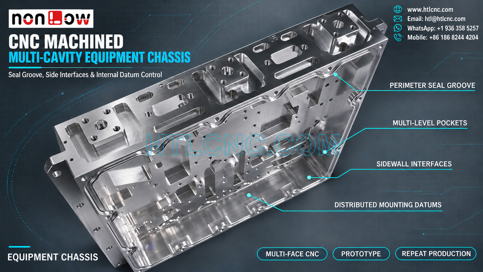
A CNC machined multi-cavity equipment chassis combines deep internal pockets, a continuous perimeter seal groove, distributed mounting features and cross-face interfaces that require coordinated machining and inspection.
A CNC machined multi-cavity equipment chassis concentrates deep pockets, stepped internal platforms, a continuous perimeter seal groove, dense hole patterns and sidewall interfaces into one structural housing. The selected photograph clearly shows one large metallic chassis with those visible features, but it does not establish the material grade, sealing standard, electronics, environmental rating, tolerance, finish or final equipment. HTL CNC provides drawing-based custom CNC machining for overseas OEMs, equipment builders, product-development companies and procurement teams that need prototype validation, documented inspection and repeat production.
Start with the Functional Interface Map
The chassis should be reviewed as a network of related interfaces rather than a collection of independent pockets. The engineering package should identify the primary seating plane, cover or mating-frame relationship, functional mounting platforms, locating holes, threaded holes, side openings and protected seal path. A simplified assembly map can show these relationships without disclosing unrelated system details.
For quotation, send the released 2D drawing, STEP model, exact material and condition, prototype and production quantities, annual demand, finish, critical tolerances, inspection requirements, packaging and destination. HTL's custom CNC machining service uses that package to review stock strategy, fixture access, datum transfer, tool reach and measurement feasibility.
Select Stock and Roughing Strategy from the Complete Geometry
The visible part has a deep open cavity with many local steps and substantial material removed from the interior. A supplier cannot choose billet, near-net stock or another route from appearance alone. The decision depends on the released geometry, material, wall thickness, tolerance, quantity and any customer restrictions.
For billet machining, roughing should create a stable load path before critical platforms and sealing surfaces are finished. Balanced material removal, staged semifinishing and free-state checks can help reveal movement before the final dimensions are cut. If another stock form is specified, the drawing must distinguish as-formed surfaces from machined interfaces.
Treat the Perimeter Seal Groove as One Continuous Feature
The image shows a shaped groove around the cavity perimeter. Its presence supports a seal-interface discussion, but the photograph does not prove gasket type, pressure, ingress rating or allowable leakage. The drawing should define groove path, width, depth, corner radii, local interruptions, surface condition and relationship to the mating face.
Inspection should verify continuity around the complete route, not only a few straight segments. Depth and width may be checked at selected sections while CMM or optical data evaluates path position. Functional sealing tests require customer-defined hardware, compression conditions and acceptance criteria; dimensional inspection alone cannot certify sealing performance.
Control Multi-Level Pockets from a Common Datum Structure
The cavity contains raised platforms, recessed zones, local walls and numerous mounting holes at different heights. Each level should be grouped by the component or interface it supports. The drawing should state which height, flatness, profile and hole-position requirements refer to the primary datum plane and which are ordinary clearance features.
A pocket can meet its local depth while still being mislocated relative to a neighboring platform. First-article reporting should therefore retain the common coordinate system across floor levels, bosses and holes. This also makes engineering changes easier to compare during prototype iterations.
Plan Tool Reach for Deep Internal Features
Deep walls and narrow internal regions can restrict cutter diameter, holder clearance and chip evacuation. Excessive tool extension may increase deflection or leave inconsistent wall texture. The supplier should review minimum corner radii, undercut risk, access direction and whether any geometry requires a secondary setup or specialized tooling.
Buyers can reduce avoidable cost by identifying truly functional radii and allowing practical relief where assembly permits. Any supplier-proposed change must be returned to the customer for drawing approval; the photograph is not authority to simplify the cavity.
Coordinate Sidewall Interfaces Across Setups
The upper edge in the selected view contains several openings, machined pads and fastener patterns on a face perpendicular to the cavity floor. These interfaces may be reachable by indexed workholding or coordinated multi-axis machining depending on the full model and tolerance. HTL's 5-axis CNC machining capability can be evaluated when it improves access or datum continuity; axis count by itself does not guarantee accuracy.
A side opening should be inspected relative to the internal feature it serves, not only from the nearest outside edge. The drawing should define profile, corner condition, thread or bore details, angular orientation and positional relationship to the primary datum structure.
Separate Locating, Fastening and Clearance Holes
Many holes are visible on the cavity floor, platforms, sidewalls and mounting flanges. Their functions cannot be identified reliably from the image. A controlled hole schedule should distinguish locating bores, threaded holes, clearance holes, dowel features and inspection points, with size, depth, position, thread callout and acceptance method.
This classification supports sensible process control. Locating features may require tighter coordinate inspection, threads need the specified gauges, and ordinary clearance holes may be sampled according to the approved plan. Treating every hole identically can add cost while missing the features that control assembly.
Protect Thin Walls and Open Flanges During Fixturing
The deep cavity leaves long perimeter walls and open mounting flanges that may respond to clamp force. A fixture should support stable regions without masking required cutting access or forcing a distorted shape. The inspection plan should state whether flatness and profile are accepted free-state, on defined supports or restrained in a customer fixture.
Setup qualification can record fixture revision, support points and clamping sequence. Rechecking critical datums after release helps separate actual machining error from temporary fixture deformation.
Define Finish and Cleanliness without Guessing from Appearance
The metallic rendering in the poster is presentation artwork and does not prove the source material or final treatment. The purchase specification should state material, finish standard, coating allowance, masking zones, cosmetic surfaces, rack-contact policy and required certificates. Seal lands, locating bores, threads and grounding areas may need different treatment instructions.
Deep pockets and intersecting holes can retain chips, abrasive residue or process fluid. If cleanliness matters, the customer should define wash method, particle or residue limits, inspection procedure and packaging. Final visual inspection should include hidden corners, threaded holes and the complete seal groove.
Build the First-Article Report around Datum Relationships
A useful first-article report can organize results by primary plane and envelope, seal groove, cavity levels, mounting platforms, hole families, sidewall interfaces and outer flanges. It should identify part revision, datum setup, free or restrained condition, measuring equipment and any customer-approved functional gauges.
CMM probing, depth instruments, height measurement, pins, thread gauges and optical profile inspection may all contribute. A related guide to patterned-interior equipment enclosure machining discusses additional boss, wall and internal-interface relationships for complex enclosure components.
Validate Assembly before the Production Route Is Locked
Prototype review should place the chassis on its defined supports, install representative internal modules or checking masters, verify side-interface alignment, fit the mating cover or frame and evaluate the specified seal hardware. This sequence can expose tool-access, hole alignment, connector clearance and closure issues before production fixtures and inspection sampling are fixed.
HTL's prototype and low-volume CNC machining service supports engineering samples and pilot lots. Approved changes should update the 2D drawing and STEP model under one controlled revision so machining, inspection and purchasing do not follow conflicting definitions.
Transfer the Approved Chassis into Repeat OEM Supply
Repeat production depends on controlled stock specification, CNC program revision, fixture identification, tool-life rules, first-piece approval, gauge calibration and documented change control. Annual demand and batch size should be shared early because they influence fixture investment, inspection sampling, raw-material planning and delivery cadence.
Packaging should prevent metal-to-metal contact around seal lands, flanges and approved cosmetic surfaces. Formed trays, nonabrasive separators or individual sleeves may be selected for the specified finish and export route. Labels should connect part number, revision, lot and quantity to inspection records.
RFQ Checklist for a Multi-Cavity Equipment Chassis
Send the released 2D drawing and STEP file, functional interface map, exact material and condition, prototype and production quantities, annual demand, primary datum scheme, cavity levels, seal-groove definition, complete hole schedule, sidewall interfaces, outer-flange requirements, tolerances, finish and masking notes, cleanliness criteria, first-article scope, packaging, destination and target delivery schedule.
A complete package allows HTL CNC to quote the CNC machined multi-cavity equipment chassis as a controlled multi-face machining and inspection program rather than estimating function from a photograph. For engineering review and quotation, visit www.htlcnc.com, email htl@htlcnc.com, send WhatsApp to +1 936 358 5257, or call mobile +86 186 8244 4204.
Have a part ready for engineering review?
Send your drawing, STEP file, material and quantity directly to HTL CNC for a manufacturing quotation.