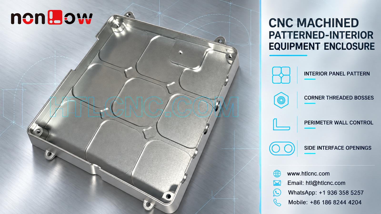
A CNC machined patterned-interior equipment enclosure coordinates recessed internal panels, corner threaded bosses, perimeter walls and side openings through one drawing-based datum and inspection plan.
A CNC machined patterned-interior equipment enclosure combines a broad internal floor, repeated recessed panel fields, a perimeter wall, corner threaded bosses and openings on multiple side faces. The selected photograph visibly supports those geometric observations. It does not establish the material grade, manufacturing origin of the blank, sealing level, shielding performance, load rating, finish specification or end application. For an overseas OEM sourcing decision, those requirements must come from the released drawing, 3D model and assembly data. HTL CNC supports prototype and repeat production of custom enclosure bodies from customer-controlled technical files.
Start the RFQ with the Assembly Interfaces
The enclosure should be quoted from its functional relationships, not from its visual similarity to another housing. Identify the primary seating plane, the cover or mating perimeter, the fastener pattern, each side opening and any external mounting tabs. State which surfaces locate the enclosure in the final assembly and which features only provide clearance.
A complete RFQ should include the 2D drawing, STEP file, mating-component data where available, exact material and condition, prototype and production quantities, annual demand, finish, critical tolerances, inspection-document scope, packaging, destination and required delivery date. Mark controlled cosmetic regions and surfaces that may accept normal workholding evidence.
Relate the Interior Pattern to One Datum Structure
The visible floor contains repeated rounded rectangular fields and smaller connecting details. These features should be defined as one controlled pattern relative to the functional datum system. A drawing that dimensions each field from a different nearby edge can hide accumulated error and make inspection unnecessarily ambiguous.
Specify which pattern boundaries affect component clearance, support or assembly. If the internal geometry is nonfunctional, avoid assigning tighter profile or location limits than the assembly requires. HTL's custom CNC machining service reviews datum selection, machining access and measurement feasibility before the setup route is finalized.
Control Corner Threaded Bosses as a Fastener Stack
Threaded bosses near the corners are more than isolated holes. Their face height, thread axis, position and relationship to the mating perimeter determine whether a cover or neighboring component can seat and fasten consistently. Define thread form, depth, entry treatment, minimum full thread and any insert requirement on the released drawing.
If screws pass through a separate cover, provide the cover-hole pattern and intended fastener stack. The photograph alone cannot confirm thread size, engagement or torque. Prototype inspection can combine thread gauges with positional measurement and a customer-approved mating check.
Preserve Perimeter-Wall Geometry During Machining
A relatively broad enclosure floor surrounded by a continuous wall can change shape as material is removed and clamps are released. Process planning should consider stock condition, remaining wall thickness, unsupported spans, roughing balance and the sequence used to finish the floor, perimeter and bosses.
Flatness, parallelism, perpendicularity and profile solve different assembly risks. The buyer should define only the controls that matter and specify whether inspection occurs in the free state or in a defined restrained condition. A fixture that forces the enclosure flat can conceal distortion that reappears during assembly.
Coordinate Side Openings with the Internal Features
The source image shows openings and projecting details on side regions. Their function is not visible, so the drawing must define each diameter or profile, axis, depth, thread or counterbore, edge distance and relationship to the selected datums. Mating connector or tube models are useful when clearances are tight.
Cross-face work can be produced by qualified refixturing, indexed machining, 5-axis CNC machining or another controlled route. The right choice depends on tolerance, access, batch size and the cost of datum transfer—not on the number of axes alone.
Plan Tool Access Around Bosses and Walls
Interior bosses and the perimeter wall can restrict cutter reach. Short, rigid tools are preferred where geometry permits, while deeper regions may require staged tools and carefully controlled stick-out. The machining plan should also consider chip evacuation from corners and avoid leaving recut debris against finished surfaces.
Any corner radius or internal transition that affects assembly should be explicit in the model and drawing. If a mating part must sit close to a wall, provide its keep-out envelope so manufacturability can be checked before production tooling is committed.
Separate Dimensional Requirements from Appearance
The metallic photograph does not prove alloy, temper, coating or surface treatment. Purchase documents should state the exact material standard and condition, finish process, coating allowance, masking locations, color or gloss requirements, cosmetic zones and certification scope.
Threads, locating faces and side openings may need post-finish control. Clarify whether dimensional limits apply before or after finishing. An approved visual sample can define acceptable appearance, but it should not replace measurable requirements for functional faces.
Build Inspection Around Feature Relationships
A risk-based first-article report may include the primary seating plane, overall envelope, perimeter-wall profile, corner-boss position and height, thread verification, internal-pattern location, side-opening position and drawing-defined geometric tolerances. Record the drawing revision, datum setup, finish condition and any inspection restraint.
CMM measurement, height systems, thread gauges, pin gauges, optical equipment and customer-approved functional fixtures can be combined according to feature risk. Individual dimensions are useful, but the inspection plan should also prove that bosses, wall, pattern and side interfaces remain coordinated within one assembly datum structure.
Use Prototype Builds to Close Assembly Risk
Prototype quantities allow the engineering team to evaluate mating-part seating, screw alignment, side-interface clearance, internal component envelope, edge access and assembly sequence. Any sealing, thermal, electrical, structural or environmental performance requires customer-defined tests and acceptance criteria; none should be inferred from a product photograph.
HTL's prototype and low-volume CNC machining service supports engineering samples and pilot lots before dedicated fixtures and sampling plans are fixed. Approved findings should update the 2D drawing, STEP file, bill of materials and inspection plan under one revision.
Transfer the Approved Enclosure into Repeat Supply
Repeat production should lock the approved stock source, fixture identification, CNC program revision, tool-life controls, first-piece approval and sampling frequency. Threaded bosses, wall profile and side openings deserve defined in-process checks because they connect directly to downstream assembly.
Packaging should prevent metal-to-metal contact and protect perimeter edges, mounting tabs and finished interfaces. Labels should identify part number, revision, quantity and production lot. Export packaging can be selected after finish sensitivity, route and customer handling requirements are known.
RFQ Checklist for a Patterned-Interior Equipment Enclosure
Send the released 2D drawing and STEP file, mating models, material and condition, prototype and repeat quantities, annual demand, datum scheme, internal-pattern definition, wall and boss controls, complete thread callouts, side-opening details, edge-break requirements, finish, inspection records, packaging, destination and target delivery. For a related enclosure topic, see our guide to equipment-enclosure internal pocket and frame datum control.
With this information, HTL CNC can review the CNC machined patterned-interior equipment enclosure as a controlled machining and inspection program rather than guessing performance from visible geometry.
Website: www.htlcnc.com Email: htl@htlcnc.com WhatsApp: +1 936 358 5257 Mobile: +86 186 8244 4204
Have a part ready for engineering review?
Send your drawing, STEP file, material and quantity directly to HTL CNC for a manufacturing quotation.