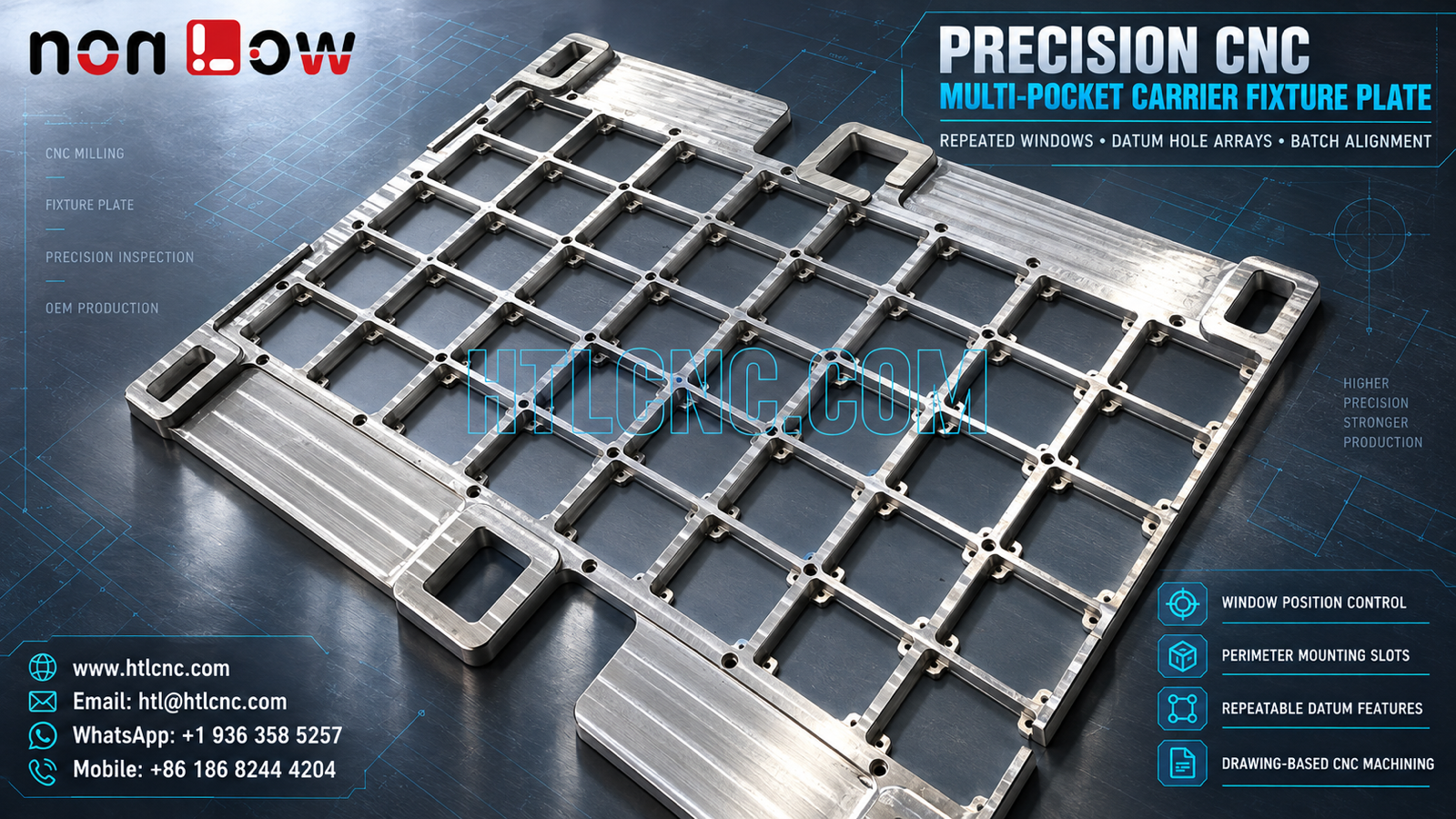
A CNC machined multi-pocket carrier fixture plate uses repeated rectangular windows, local corner reliefs, datum-hole arrays and perimeter mounting slots that must remain consistent across every station.
A CNC machined multi-pocket carrier fixture plate is a large plate-style component with many repeated stations that must behave as one coordinated interface. The selected photograph visibly shows one wide machined carrier with a dense grid of rounded-rectangle windows, small local corner reliefs, holes at repeated intersections, broad reinforced end zones and elongated perimeter mounting slots. The image does not establish material grade, exact tolerance, finish specification, mating product or final production use. HTL CNC manufactures drawing-based custom CNC parts for overseas OEMs, product-development teams, equipment builders, contract manufacturers, engineers and procurement teams from prototype validation through low-volume and repeat production.
Why Repeated Stations Change the Sourcing Risk
A multi-station fixture plate cannot be evaluated as a collection of unrelated cutouts. A small pitch error can accumulate across the grid, while local window size may remain within tolerance. The RFQ should therefore define the station coordinate system, primary seating plane, pitch in both directions, allowable pattern error and the features that locate the carrier in the customer's equipment.
Procurement teams should ask how the supplier will preserve the same datum structure through machining and inspection. HTL's custom CNC machining service reviews the released 2D drawing, STEP model and mating-interface data before fixture design and process release.
Establish One Master Datum Scheme for the Full Plate
The visible carrier includes a broad external envelope, end extensions, repeated holes and mounting slots. Raw-stock edges should not automatically become inspection datums if the actual assembly locates from a machined face, a selected hole pair or a perimeter slot. The drawing should identify the primary plane, direction feature and rotation-control feature explicitly.
A master datum structure lets the supplier relate the outside profile, every station center and the equipment-mounting features to the same coordinate system. It also gives the buyer a consistent basis for first-article reports and future repeat-order comparison.
Define Each Window as a Controlled Station Profile
The photograph shows many rectangular openings with rounded corners and small local tabs or reliefs near the corners. Overall window length and width alone may not control the complete interface. The released model should define corner radii, local relief geometry, edge breaks, permissible cutter radii and any surfaces that contact or clear a mating component.
When one station is nominally repeated, the drawing should state whether all stations share one profile definition or whether selected positions have unique geometry. A station map prevents the supplier from copying a typical opening into a location that carries a deliberate exception.
Control Grid Pitch Without Long Chain Dimensions
Long coordinate chains can allow tolerance accumulation from one end of the carrier to the other. Basic coordinates or another clear pattern-control method may be more appropriate when every window must align with a common downstream interface. The customer's drawing authority determines the final tolerancing method.
Inspection can compare individual window centers, row and column pitch, diagonal relationships and the complete pattern relative to the master datums. A CMM, optical system or approved checking master may be selected according to plate size, tolerance and access.
Keep Datum-Hole Arrays Separate from Fastener and Clearance Holes
Small holes appear at many intersections and around the perimeter, but the photograph cannot prove which are locating, threaded, fastener, clearance or inspection features. A complete hole schedule should identify size, depth, thread or ream requirement, counterbore or countersink details, position control and final acceptance method.
If only a few holes establish station location while others provide fastening clearance, that functional difference should be visible in the drawing and inspection plan. Treating every hole as equivalent can increase cost while still missing the locations that control actual assembly.
Plan Material Removal to Protect Flatness and Narrow Webs
A dense window array leaves thin webs between adjacent stations and creates an interrupted load path through the plate. Clamp force and cutting sequence can temporarily flatten or twist the carrier, especially after most interior material has been removed. The drawing should state whether flatness and profile are checked free-state or under defined restraint.
A qualified route may combine balanced roughing, temporary support, distributed workholding, controlled flip operations and final machining of critical interfaces after the structure stabilizes. The correct sequence depends on exact material, plate thickness, tolerance and quantity; it cannot be determined from the photograph alone.
Treat Perimeter Slots as Equipment-Mounting Interfaces
Several elongated slots are visible in the reinforced outer zones. These may support mounting or adjustment, but their exact function is not proven. Slot length, width, end radii, local step geometry and positional relationship to the master datums should be fully controlled if they locate the carrier in equipment.
Prototype validation should confirm fastener access, installation travel and edge clearance with the actual machine or an approved interface master. Any permitted adjustment should be distinguished from features that establish repeatable location.
Build First-Article Inspection Around Pattern Behavior
A useful first-article report should do more than list a few typical window dimensions. It can include the overall envelope, plate thickness, primary-plane flatness, perimeter slots, selected station profiles, row and column pitch, end-to-end pattern location, datum-hole features and drawing-defined geometric tolerances.
The report should identify the drawing revision, datum setup, measurement method and free or restrained condition. Overseas buyers should also specify whether they require material documents, a full dimensional report, station sampling, capability data or lot-level inspection records.
Validate the Carrier with a Station Map and Mating Samples
Prototype approval is stronger when the engineering team checks more than the first opening. A station map can record representative locations near the center, edges and corners, where stiffness and accumulated position error may differ. Real mating samples or a functional checking master can verify seating, clearance and removal at those positions.
HTL's prototype and low-volume CNC machining service supports engineering samples and pilot quantities before production fixtures and inspection routines are locked. Approved corrections should update the 2D drawing and STEP model under the same controlled revision.
Transfer the Approved Plate into Repeat OEM Production
After prototype acceptance, repeatability depends on locking the CNC program, workholding revision, datum method, station map, tool-life rules and inspection plan. A replacement fixture or process change should trigger defined requalification rather than relying on visual similarity.
Packaging should support the broad plate without concentrating load on narrow webs or exposed window edges. Interleaving sheets, perimeter supports or a dedicated export crate may be required according to size, finish and shipping route. Delivery planning should consider prototype quantity, annual demand, batch size and inspection-document lead time.
Prepare a Complete RFQ for the Carrier Plate
Send the released 2D drawing and STEP file, exact material, prototype and production quantities, annual demand, master datum scheme, station map, window profiles, pitch tolerances, hole schedule, perimeter-slot requirements, flatness condition, surface finish, inspection-document scope, packaging, destination and delivery target. Include the mating component or a simplified interface master when station fit is critical. Confidential drawings can be reviewed under the buyer's required document-control process.
This information allows HTL CNC to quote the CNC machined multi-pocket carrier fixture plate as a repeatable production interface instead of estimating from a photo. Teams sourcing other complex plate geometry can also review our guide to precision CNC multi-opening fixture plate datum control.
Website: www.htlcnc.com Email: htl@htlcnc.com WhatsApp: +1 936 358 5257 Mobile: +86 186 8244 4204
Have a part ready for engineering review?
Send your drawing, STEP file, material and quantity directly to HTL CNC for a manufacturing quotation.