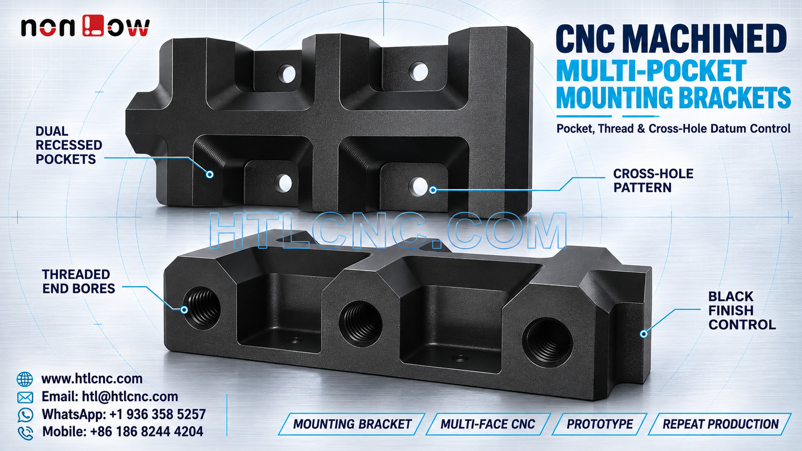
CNC machined multi-pocket mounting brackets combine recessed bays, transverse holes, threaded end bores and a black finish that must remain coordinated through prototype approval and repeat OEM supply.
CNC machined multi-pocket mounting brackets bring recessed bays, raised ribs, transverse holes, threaded end bores and multiple exterior faces into one compact structural component. The selected photograph shows two examples of the same black-finished bracket geometry from complementary orientations. Those visible features support a multi-face bracket machining topic, but they do not establish the material, coating chemistry, thread standard, tolerance, load or final equipment. HTL CNC provides drawing-based custom CNC machining for overseas OEMs, equipment builders, product-development teams and procurement organizations from prototype review through repeat production.
Qualify the Bracket from Its Mating Interfaces
A supplier needs to know what seats inside each recessed pocket, which cross holes locate or fasten the assembly, and what engages the threaded end bores. Simplified mating envelopes or customer-approved sample components help separate functional surfaces from ordinary clearance without exposing unrelated system details.
A complete RFQ should include the released 2D drawing, STEP model, exact material and condition, thread definitions, prototype and production quantities, annual demand, finish, inspection documents, packaging and destination. HTL's custom CNC machining service reviews those inputs before fixture and process planning.
Establish a Datum Scheme before Cutting the Pockets
The long bracket has several broad exterior faces that could appear suitable for workholding, but the manufacturing datum should follow assembly function rather than convenience. The drawing should identify the primary seating plane, the feature that controls longitudinal position and the feature that prevents rotation.
Every recessed bay, transverse hole and end bore can then be related to one common coordinate system. This prevents local dimensions from passing while the complete bracket fails to align with its mating structure.
Control Repeated Recessed Bays as a Pattern
The visible part includes four open pockets divided by central ribs and end walls. Pocket length, width and depth matter, but so do corner radii, wall position, floor height, rib thickness and the pitch between repeated regions. The drawing should show whether all bays share one typical definition or contain deliberate exceptions.
Inspection can compare representative pocket profiles and the complete pattern relative to the primary datums. A CMM, depth instrument or approved checking master may be selected according to tolerance and access. Visual similarity between pockets is not dimensional evidence.
Relate Cross Holes to Pocket Floors and Walls
Small transverse holes pass through local tabs inside the recesses. Their exact function is not confirmed by the image. If they locate pins or fasteners, the drawing should define size, positional tolerance, edge condition and relationship to the pocket floor, sidewalls and bracket datum structure.
A hole can meet diameter while missing the centerline of a mating component. Prototype inspection should therefore record both size and location. When alignment is assembly-critical, a customer-approved pin or mating gauge can complement coordinate measurement.
Define the Threaded End Bores Completely
Several large threaded bores are visible on the angled sample. The photograph cannot identify thread form, nominal size, pitch, class, handedness, engagement length or required insert. The purchase drawing must state the complete thread callout, entry chamfer, usable depth, bottom condition and gauge method.
Thread gauges confirm fit limits but do not prove that a bore axis is correctly located or oriented. The first-article plan should include bore position and axis relationship where they affect assembly, plus any customer-defined torque or pull test that is genuinely required.
Manage Multi-Face Machining and Datum Transfer
The pockets, cross holes and threaded bores face different directions. A process may use indexed workholding, qualified secondary setups or coordinated multi-axis access depending on geometry and tolerance. HTL's 5-axis CNC machining capability can be evaluated when it reduces setup changes or improves access; machine axis count alone is not a quality claim.
When multiple setups are used, the supplier should identify the transfer datums and protect them from clamp damage. Setup qualification can record fixture revision, locating sequence and first-piece checks so repeat batches use the same relationship.
Protect Ribs and Open Pockets during Deburring
The recessed geometry creates interrupted edges, internal corners and narrow wall transitions. A blanket deburring note may be insufficient when a mating part seats near those edges. The drawing should distinguish controlled chamfers or radii from edges that only require safe burr removal.
Deburring should not round pocket datums, change cross-hole edges or damage thread entries. Deep corners and intersecting holes also need a cleanliness check so chips and abrasive residue are not trapped before finishing or shipment.
Specify the Black Finish as a Process Requirement
The photograph confirms a dark appearance but cannot identify the substrate or surface treatment. The purchase order should state material, finish standard, color and texture, coating allowance, masking zones, cosmetic acceptance, rack-contact policy and required certificates.
Threads, locating holes, pocket floors and seating faces may need different treatment instructions. If coating thickness changes a fit, the drawing should state whether the controlled dimensions apply before or after finishing and whether post-finish gauging is required.
Organize First-Article Inspection around Assembly Risk
A useful first-article report can cover the primary datum plane, overall envelope, repeated pocket pattern, rib and wall locations, cross-hole groups, threaded end bores, external mounting faces and drawing-defined geometric tolerances. It should identify drawing revision, fixture condition, measuring equipment and gauge IDs.
A related guide to open-frame equipment bracket machining discusses additional cross-face datum and cutout-pattern issues for structural bracket components.
Use Prototype Quantities to Confirm Real Fit
Prototype validation should place the bracket against its actual mounting interface, install representative components in the pockets, pass the required pins or fasteners through the transverse holes and engage the specified threaded hardware. This sequence checks cumulative alignment, access and assembly order before production fixtures and sampling plans are locked.
HTL's prototype and low-volume CNC machining service supports engineering samples and pilot lots. Approved changes should update the 2D drawing and STEP model under one controlled revision.
Transfer the Approved Bracket into Repeat Supply
After prototype approval, repeat-order consistency depends on controlled stock, CNC program revision, fixture identification, tool-life rules, first-piece release, thread-gauge calibration and formal change control. Sharing annual demand and batch size helps the supplier plan raw material, fixtures, inspection capacity and delivery cadence.
Packaging should prevent the black finish, pocket edges and thread entries from rubbing against other parts. Nonabrasive separators, formed trays, thread protection or individual sleeves may be selected for the actual finish and export route.
RFQ Checklist for Multi-Pocket Mounting Brackets
Send the released 2D drawing and STEP file, mating-interface information, exact material and condition, prototype and production quantities, annual demand, datum scheme, pocket pattern, cross-hole definitions, complete thread callouts, tolerances, black finish and masking notes, inspection-document scope, packaging, destination and target schedule. Confidential files can be reviewed under the buyer's required document-control process.
This package allows HTL CNC to quote the CNC machined multi-pocket mounting brackets as a controlled multi-face machining and inspection program rather than estimating function from a photograph. For engineering review and quotation, visit www.htlcnc.com, email htl@htlcnc.com, send WhatsApp to +1 936 358 5257, or call mobile +86 186 8244 4204.
Have a part ready for engineering review?
Send your drawing, STEP file, material and quantity directly to HTL CNC for a manufacturing quotation.