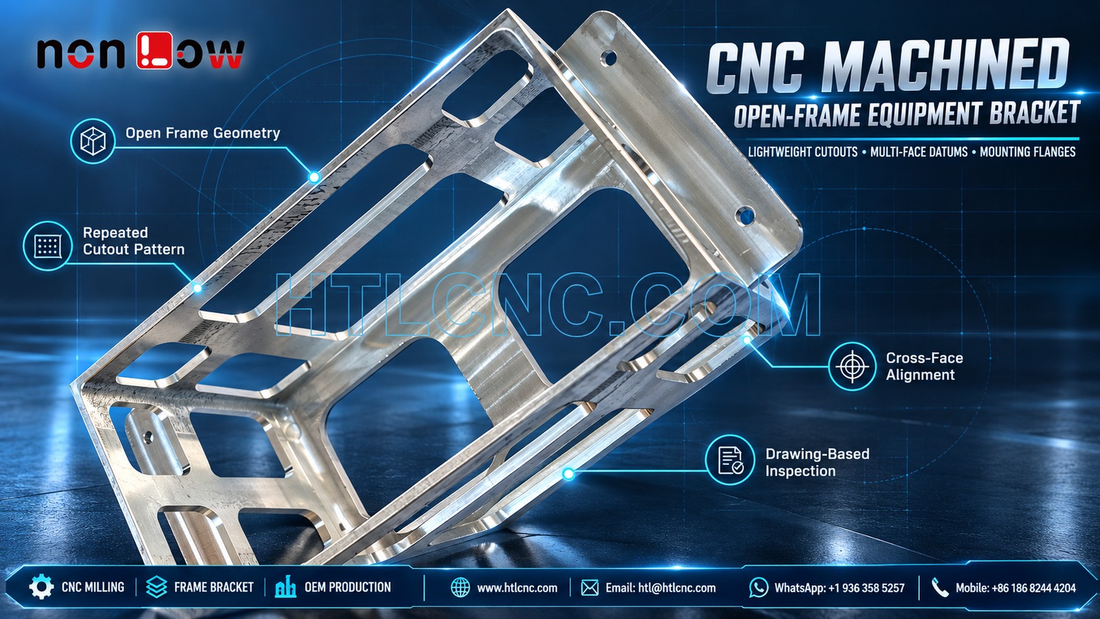
A CNC machined open-frame equipment bracket combines repeated lightweight openings, long rails, end walls and mounting flanges that must remain coordinated through multi-face milling and inspection.
A CNC machined open-frame equipment bracket uses strategically removed material to create access and reduce mass while preserving a connected three-dimensional frame. The selected photograph visibly shows one long metallic bracket with repeated rounded rectangular cutouts, elongated slots, two end walls, side rails, a projecting mounting flange and holes on more than one face. These observations support an open-frame bracket machining topic, but the image does not prove material grade, load, stiffness target, tolerance, finish chemistry or final application. HTL CNC provides drawing-based custom CNC machining for overseas OEMs, product-development companies, equipment builders, engineers and procurement teams from prototype sourcing through repeat production.
What Is an Open-Frame Equipment Bracket?
An open-frame equipment bracket is a structural or mounting component whose connected walls and rails surround multiple access or weight-reduction openings. Its function must come from the released assembly, not from appearance. In an RFQ, identify which faces mount to the machine, which openings provide access or clearance, and which rails or flanges locate neighboring parts.
Send the released 2D drawing, STEP file, mating-component models, exact material and condition, prototype and production quantities, annual demand, critical tolerances, finish, inspection-document scope, packaging requirements and delivery destination. If the bracket has a customer-defined stiffness, load or vibration requirement, include the validated test method and acceptance criteria.
Map the Functional Datum Chain Across Three Dimensions
The visible geometry extends across a base region, upright end walls, side rails and a projecting flange. A practical drawing should identify one primary seating plane, one longitudinal reference and one clocking feature. The cutout pattern, end-wall profiles, flange holes and cross-face features can then share one coordinate structure.
Independent dimensions from convenient outer edges can hide accumulated error along the frame. HTL's custom CNC machining service reviews datum selection, stock route, workholding, tool access and inspection strategy before releasing a setup plan.
Treat Repeated Cutouts as One Controlled Pattern
The bracket contains several rounded rectangular openings and long slots. Each visible opening has its own position, envelope, corner radius and surrounding web. The released model should define the complete pattern rather than relying only on a typical-opening note when end features differ.
Narrow bridges between openings can be sensitive to tool engagement and clamping. A process may rough openings in a balanced sequence, preserve support until later operations and finish critical profiles after the frame is stable. Optical measurement or CMM profile checks can verify the pattern relative to the functional datums.
Protect Long Rails from Twist During Material Removal
Long open rails have less resistance to torsion than a solid block. Heavy removal from one region can release stock stress or change the way the part sits in a fixture. The supplier should review remaining wall, rail width, unsupported span and clamp location before selecting roughing and finishing passes.
Flatness, straightness, parallelism and profile are different controls. The buyer should specify only those that affect assembly and identify the inspection state. A fixture can temporarily force a flexible bracket into shape, so final checks in the free state are important unless the drawing defines a restrained condition.
Coordinate the Mounting Flange with the Frame
A projecting flange with visible holes forms a distinct interface at one end of the part. Hole diameter or thread callout alone does not control assembly. The drawing should define flange thickness, face location, hole pattern, edge distance, perpendicularity or profile, and the relationship to the primary frame datums.
If the flange mates with another bracket, panel or machine surface, provide that mating geometry and the required fastener stack. The photograph cannot establish whether visible holes are clearance, threaded, countersunk or counterbored features. Those details belong in the 2D drawing and inspection plan.
Select the Machining Route from Access and Relationship Control
The open geometry provides access from several directions, but it also creates many cross-face relationships. Depending on the complete model, tolerance and quantity, production may use qualified 3-axis refixturing, indexed 4-axis workholding, 5-axis CNC machining or another controlled route. More axes are useful only when they reduce uncertain datum transfers or improve tool access.
Machine selection should also consider cutter reach, chip evacuation, wall vibration and inspection access. Prototype fixtures may prioritize flexibility, while recurring orders may justify a dedicated nest that locates approved datum features without loading thin rails.
Define Edge Breaks Without Weakening the Webs
Every cutout creates exposed edges and internal corners. A generic deburr instruction can be insufficient when a rail is narrow or an opening interfaces with a cable, connector, guard or other component. Specify required chamfers or radii, maximum allowed edge break and any edge that must remain functionally sharp.
Manual finishing should not widen openings, thin the connecting webs or change flange seating surfaces. The acceptance method may combine visual inspection, magnification, edge comparators and an approved cosmetic or tactile sample according to the real assembly risk.
Keep Material and Finish Requirements Evidence-Based
The bright metallic appearance does not prove an alloy, temper, plating or final finish. The purchase documents should state the material standard and condition, heat treatment where applicable, surface process, coating allowance, cosmetic zones, masking locations, corrosion requirement and certification scope.
Mounting faces, locating holes and threaded features may need post-finish dimensional control. The drawing should say whether limits apply before or after treatment. If appearance matters, define texture direction, color or gloss range, viewing conditions and allowable handling marks separately from dimensional acceptance.
Build First-Article Inspection Around Relationships
A risk-based first-article report may include the primary seating plane, overall envelope, long-rail straightness, repeated cutout profiles, remaining web widths, end-wall relationship, flange position, mounting-hole pattern and drawing-defined geometric tolerances. The report should identify the part revision, datum setup, finish condition and whether the frame was restrained.
Measurement can combine height systems, pin and depth gauges, optical equipment, CMM probing and customer-approved functional fixtures. Individual opening sizes are useful, but the buyer also needs evidence that the complete cutout pattern and flange remain aligned to the same assembly datums.
Validate the Prototype with Mating Components
Prototype quantities allow the engineering team to check bracket seating, fastener access, opening clearance, cable or tool access where relevant, neighboring-part spacing and assembly sequence. Structural, vibration, fatigue or impact performance requires customer-defined fixtures, loads, cycles and pass criteria; it cannot be inferred from a photograph.
HTL's prototype and low-volume CNC machining service supports engineering samples and pilot lots before dedicated fixtures, process limits and sampling plans are fixed. Approved changes should update the 2D drawing, STEP model, assembly file and inspection plan under one controlled revision.
Transfer the Approved Frame into Repeat OEM Production
Repeat supply depends on controlled stock sources, fixture identification, CNC program revision, first-piece approval, tool-life rules and in-process checks on rail and flange relationships. The accepted datum-transfer method should remain in the setup documentation rather than relying on operator memory.
Packaging should protect thin rails, cutout edges and mounting faces from impact or metal-to-metal contact. Formed trays, separators, protective films or individual sleeves may be selected according to finish sensitivity and export route. Labels should identify part number, revision, quantity and production lot.
RFQ Checklist for a CNC Machined Open-Frame Equipment Bracket
Provide the released 2D drawing and STEP file, assembly and mating-part data, exact material and condition, prototype and production quantities, annual demand, functional datums, cutout and slot definitions, minimum web and wall requirements, flange and hole details, geometric controls, edge-break standard, finish, inspection-document scope, packaging, destination and target delivery. Confidential technical files can be reviewed under the buyer's required document-control process.
A complete package allows HTL CNC to quote the CNC machined open-frame equipment bracket as a controlled multi-face milling and inspection program rather than guessing strength or application from visible geometry. For a related frame-and-cavity topic, review our guide to CNC machined equipment enclosure datum control.
Website: www.htlcnc.com Email: htl@htlcnc.com WhatsApp: +1 936 358 5257 Mobile: +86 186 8244 4204
Have a part ready for engineering review?
Send your drawing, STEP file, material and quantity directly to HTL CNC for a manufacturing quotation.