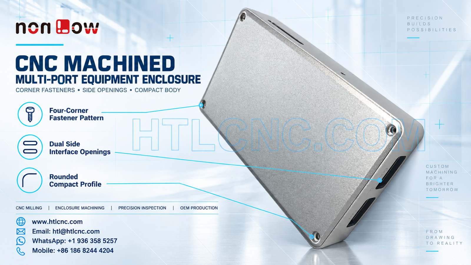
A CNC machined multi-port equipment enclosure brings corner fasteners, side interface openings, a compact rounded body and cover geometry into one coordinated drawing-based component.
A CNC machined multi-port equipment enclosure may appear visually simple, yet its assembly performance depends on several surfaces and openings remaining related to one stable datum system. The selected photograph visibly shows one compact rectangular metallic enclosure with softly rounded corners, four corner fastener locations, a fitted top cover and multiple openings on adjacent side faces. The image does not establish material grade, exact tolerance, coating, sealing level, thermal duty, connector type or final application. HTL CNC manufactures drawing-based custom components for overseas OEMs, R&D teams, equipment builders, engineers and procurement groups from prototype review through repeat production.
Start with the Assembly Datum Structure
The released drawing should identify the face that seats the enclosure in the final assembly, the feature that controls direction and the feature that prevents rotation. A broad cover surface or raw-stock edge should not become the default datum simply because it is easy to reach.
A functional datum structure lets the supplier relate the outside envelope, cover interface, corner fasteners and side openings to the same coordinate system. HTL's custom CNC machining service reviews the 2D drawing, STEP model and mating-interface information before workholding and inspection methods are released.
Coordinate the Four-Corner Fastener Pattern
Four recessed fastener locations are visible near the cover corners. The photograph cannot confirm whether they are clearance holes, countersinks, counterbores or threaded features. The drawing should define diameter, depth, angle or thread, edge distance, positional tolerance and the surface from which depth is measured.
Corner holes should be controlled as a pattern when the cover and body must assemble without forcing. If a separate lid is supplied, both components need a common coordinate definition and matching revision. Inspection can then verify pattern position rather than accepting four unrelated hole sizes.
Define Side Openings as Functional Interfaces
The visible side faces include rounded-rectangle openings of different sizes. Their function is not proven by appearance, so connector, cable, ventilation or service claims should not be inferred. The buyer should provide opening width and height, corner radii, wall position, edge condition and true-position or profile requirements relative to the functional datums.
Mating connector models or an interface drawing are especially useful where a flange, gasket, switch or cable gland must clear the opening. HTL can evaluate qualified 3-axis refixturing, indexed machining or 5-axis CNC machining according to access, tolerance and quantity. The goal is to control relationships while minimizing unnecessary datum transfers.
Manage Cover Fit and Perimeter Geometry
A narrow perimeter transition is visible around the top cover. The photographs do not reveal the hidden joint geometry, so the released model should define any lip, rebate, groove, ledge, gap or flushness requirement. If the joint supports sealing, the customer must specify the gasket, compression target, surface finish and test method.
Cover flatness and body opening geometry can interact with corner fastener load. A visually flush cover is not proof of controlled compression or environmental protection. Prototype inspection should record the cover-to-body interface in the free state and under the specified assembly condition when that distinction matters.
Protect Thin Walls During Multi-Face Machining
Machining openings into adjacent walls changes local stiffness and leaves narrow bridges near edges and corners. Clamping force, roughing sequence and tool engagement should be planned so the enclosure is not temporarily distorted before final side features are cut. Internal support or a dedicated nest may be considered after actual wall thickness and quantity are known.
The process may leave uniform stock during roughing, finish the primary seating face, establish repeatable secondary location and then complete side openings from controlled orientations. Exact sequencing depends on material, starting stock, tolerances and finish requirements; it cannot be selected from the photograph alone.
Control Edge Breaks Around Ports and Handling Surfaces
Every side opening introduces internal corners and exposed edges. A general deburring note may not define the desired result. The drawing should distinguish controlled chamfers or radii from edges that must remain sharp within a stated limit, and it should identify surfaces that contact seals or connector flanges.
Deburring must remove loose material and handling hazards without enlarging an opening or rounding a locating edge. Optical inspection, edge comparators or customer-approved samples can support acceptance when appearance and touch condition are important.
Plan Surface Finish Without Assuming the Material
The source shows a fine metallic texture, but appearance does not identify an alloy or treatment. Material specification, temper or condition, hardness, corrosion requirement, electrical continuity and cosmetic standard should come from the purchase documents. Possible finishing routes must be reviewed only after those inputs are known.
Close-fitting openings, threads, fastener seats and cover interfaces may require masking, coating allowance or post-finish inspection. Cosmetic zones, acceptable color range, texture direction, viewing conditions and handling protection should be defined separately from dimensional acceptance.
Build First-Article Inspection Around Relationships
A useful first-article report can cover the primary seating plane, outside envelope, corner-hole pattern, side-opening profiles, distances between adjacent-face interfaces, cover geometry and drawing-defined geometric tolerances. The report should identify the datum setup, revision, measurement method and whether the part was restrained.
Measurement may combine height systems, pin and depth gauges, thread gauges, optical equipment, CMM probing and customer-approved functional masters. Critical openings should be evaluated from the same datums that govern assembly, not from a nearby edge chosen only for convenience.
Validate the Enclosure During Prototype Production
Prototype quantities allow the engineering team to confirm cover seating, fastener access, connector clearance, cable routing, internal component clearance and the proposed inspection method. Sealing, thermal, vibration, electromagnetic or life performance requires customer-defined procedures and acceptance criteria. No such performance claim can be made from a product photograph.
HTL's prototype and low-volume CNC machining service supports engineering samples and pilot lots before recurring production controls are locked. Approved changes should update the 2D drawing, STEP model, interface files and inspection plan under one coordinated revision.
Transfer the Approved Design into Repeat OEM Supply
After prototype approval, repeatability depends on controlled CNC programs, fixture identification, first-piece approval, tool-life rules, calibrated gauges and formal revision management. When machining spans several faces, the qualified transfer-datum method should remain part of the setup documentation.
Packaging should prevent metal-to-metal contact around cosmetic faces, corner holes and side openings. Individual sleeves, separators or formed trays may be selected according to the actual finish and shipping route. Labels should identify part number, revision, quantity and production lot for overseas receiving.
RFQ Checklist for a Multi-Port Equipment Enclosure
Send the released 2D drawing and STEP file, lid and assembly models, exact material and condition, prototype and production quantities, annual demand, functional datum scheme, corner-fastener definitions, side-opening profiles, wall thicknesses, tolerances, geometric controls, surface finish, cosmetic criteria, any sealing or performance test, inspection-document scope, packaging, destination and target schedule. Confidential technical files can be reviewed under the buyer's required document-control process.
This package allows HTL CNC to quote the CNC machined multi-port equipment enclosure as a controlled multi-face machining and inspection program rather than estimating from a photograph. For another compact housing example, review our guide to CNC machined square interface housing control.
Website: www.htlcnc.com Email: htl@htlcnc.com WhatsApp: +1 936 358 5257 Mobile: +86 186 8244 4204
Have a part ready for engineering review?
Send your drawing, STEP file, material and quantity directly to HTL CNC for a manufacturing quotation.