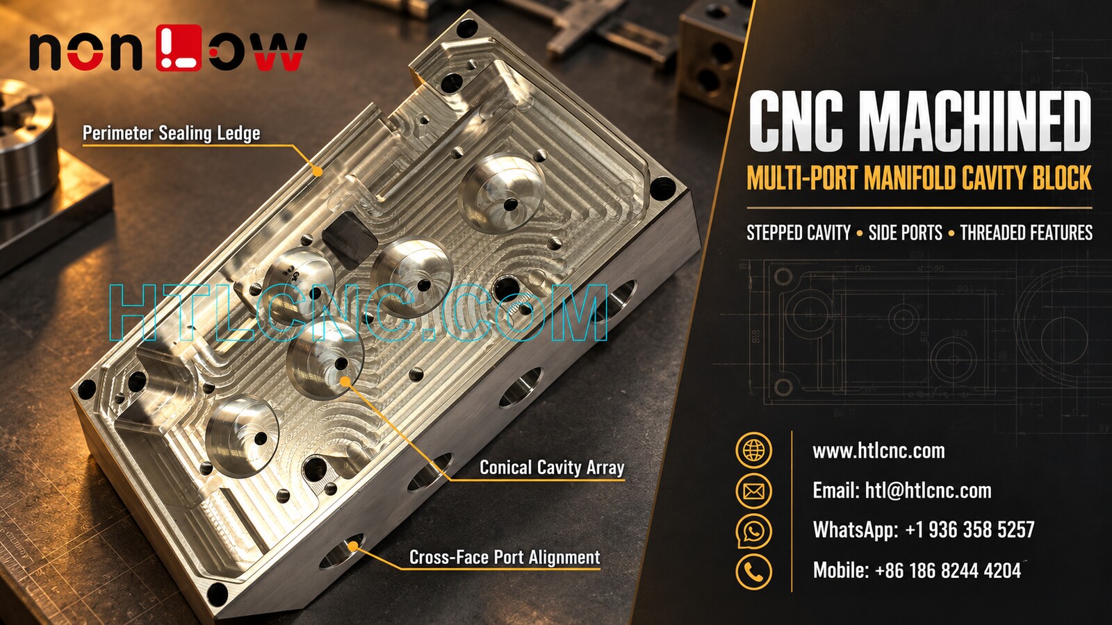
A CNC machined multi-port manifold cavity block combines a deep perimeter pocket, repeated conical cavity features, side bores and threaded interfaces that must remain coordinated across several machining orientations.
A CNC machined multi-port manifold cavity block concentrates many interacting features in one rectangular component. The selected photograph visibly shows a deep perimeter pocket, a stepped ledge around that pocket, five raised conical or circular cavity features with small center bores, multiple threaded holes, corner bores and four large openings on a side face. Those visible features support a multi-port cavity-block manufacturing topic, but the photograph does not prove the working medium, internal flow path, material grade, pressure rating, leakage criterion, dimensional tolerance or final machine. HTL CNC supports overseas OEMs, R&D companies, equipment builders, engineers and procurement teams with drawing-based prototypes, pilot quantities and repeat production.
Begin with a Functional Datum Strategy
The first manufacturing question is not which cutter to use; it is how the product will locate and seal in its assembly. The released drawing should identify the primary seating or mounting plane, the secondary direction datum and the tertiary clocking feature. These references allow the pocket, cavity array, side ports and threaded holes to be evaluated in one coordinate system.
Using a rough stock edge or a visually convenient wall as an uncontrolled reference can create acceptable local dimensions while cross-face relationships drift. HTL's custom CNC machining service reviews the 2D drawing, STEP model, mating-component data and inspection requirements before the workholding sequence is finalized.
Define the Perimeter Ledge as an Interface
A continuous stepped ledge is visible around the main recessed region. Its purpose cannot be confirmed from the image; it may locate a cover, support a gasket, provide clearance or serve another assembly function. The buyer should define ledge width, depth, flatness, profile, corner radii and position relative to the primary datum.
If sealing is required, the RFQ must also identify the gasket or seal geometry, surface-finish limit, compression condition, fastener pattern and customer test method. A visually smooth ledge is not evidence of leak performance. Dimensional inspection and product-level pressure or leakage validation should be listed as separate acceptance activities.
Control the Conical Cavity Array as a Pattern
Five raised circular features with tapered or conical internal surfaces are visible inside the pocket. The drawing should number each feature and specify its opening diameter, included angle or controlled profile, axial depth, center bore, transition radius and location. If the features are functionally related, their complete pattern position should be controlled rather than treating five diameters as independent checks.
Conical surfaces require an agreed inspection method. Depending on tolerance and access, verification may use calibrated taper gauges, CMM scanning, optical measurement, dedicated masters or section-based profile data. The method and evaluation height should be agreed before first-article production so supplier and buyer do not inspect different theoretical sections.
Maintain Cross-Face Alignment for Side Ports
Four large round ports are visible on one side wall, while the pocket and cavity features are approached from another direction. Their visible proximity does not prove that each port intersects a specific internal feature. The released model must establish any required intersection, axial offset, angular relationship, depth and breakthrough condition.
Cross-face work can be completed with controlled refixturing, indexed machining or 5-axis CNC machining, depending on geometry, tolerance, tool access and quantity. More axes are not automatically better; the selected route should minimize uncertain datum transfers and leave critical surfaces available for inspection.
Plan Machining Around Wall Stability
Removing a broad internal pocket reduces stiffness while raised bosses, side walls and narrow lands remain. Roughing strategy, stock allowance and clamping load should therefore be considered together. Excessive clamping can distort the block during finishing and allow the sealing ledge or side wall to move after release.
A qualified process may establish stable external references, rough the pocket with balanced allowance, machine selected cross-face ports, allow stress redistribution and then finish the functional interfaces. The exact sequence depends on material, blank condition, tolerance and quantity; it cannot be assigned from the photograph alone.
Specify Threads, Corner Bores and Small Holes Individually
The visible part includes several small holes and apparent threaded features around the cavity array and perimeter. Each should have a unique identifier tied to a hole table. Diameter, thread designation, depth, entry chamfer, bottom condition, positional requirement and inspection gauge must be explicit.
Blind threads near pocket floors need sufficient tap or thread-mill clearance. Intersecting holes also require a deburring plan because loose material can remain where normal visual access is poor. Thread gauges confirm size, but positional inspection is still needed when fasteners, fittings or cover holes must align as a pattern.
Control Internal Radii and Tool Access
The pocket contains long walls, local steps and several transitions around the circular features. Internal corner radii should reflect practical cutter access unless a sharper geometry has a documented function. Deep or narrow regions may require extended tooling, which can affect deflection, vibration and achievable surface condition.
The STEP model should agree with the 2D drawing on radii, reliefs, floor depths and boss transitions. If a mating component requires a near-sharp corner, a designed relief or alternate manufacturing method may be more repeatable than leaving an ambiguous zero-radius model edge.
Separate Surface Finish from Functional Testing
The metallic appearance suggests a machined surface but does not identify aluminum, alloy condition, coating or final roughness. The purchase documents should state the exact material standard, temper or heat-treatment condition, finish requirement, coating allowance, masking zones, cosmetic areas and certificate scope.
Functional interfaces may need different surface requirements from general pocket walls. A sealing ledge, conical seat, fitting bore and cover face should each carry the finish specification required by the customer's design. Pressure, vacuum, cleanliness or media-compatibility testing must be separately defined with test values and pass criteria.
Build a Risk-Based First-Article Report
A useful first-article plan can include the outside envelope, primary mounting plane, perimeter-ledged pocket, cavity-array position and profile, side-port diameters and axes, corner-bore pattern, threaded-hole positions, wall thickness and drawing-defined geometric tolerances. The report should identify part revision, datum setup, measurement equipment and restraint condition.
CMM probing may be combined with depth gauges, thread gauges, pin gauges, profilometry, optical equipment and customer-approved functional masters. Features that cannot be reached reliably after all machining should receive in-process verification at the stage when access is controlled.
Validate Assembly and Function During Prototyping
Prototype quantities let the customer's engineering team confirm mounting, cover or gasket fit, port alignment, tool or fitting access, internal clearance and the agreed inspection method. If the block handles fluid, gas, vacuum or another medium, the customer should provide the operating envelope, cleaning standard and validation protocol. No pressure or sealing claim should be inferred from a photograph.
HTL's prototype and low-volume CNC machining service can support engineering samples before fixtures, programs and inspection sampling are locked for recurring orders. Any approved design change should update the 2D drawing, STEP model, hole schedule, test specification and revision status together.
Transfer the Approved Process into Repeat OEM Supply
Repeat production depends on controlled material lots, CNC programs, fixture identification, first-piece approval, tool-life limits, calibrated gauges and formal change management. Cross-face port alignment and cavity profiles should remain linked to the same qualified datum strategy used for the approved sample.
Packaging should protect the sealing ledge, cavity edges and side-port entrances from metal-to-metal contact. Clean covers, individual separators or formed trays can be specified according to surface sensitivity and shipping route. Lot labels should identify part number, drawing revision, quantity and traceability information required at receiving.
RFQ Checklist for a Multi-Port Manifold Cavity Block
Send the released 2D drawing and STEP file, mating-part or cover model, exact material and condition, prototype and production quantities, annual demand, functional datum scheme, perimeter-ledged pocket definition, conical cavity schedule, side-port geometry, thread and hole table, cross-face relationships, tolerances, surface requirements, cleaning and functional-test specifications, first-article documentation, packaging, destination and target schedule.
A complete package allows HTL CNC to quote the multi-port manifold cavity block as a controlled machining, inspection and validation program. For another related geometry, see our guide to multi-port manifold block precision CNC machining.
Website: www.htlcnc.com Email: htl@htlcnc.com WhatsApp: +1 936 358 5257 Mobile: +86 186 8244 4204
Have a part ready for engineering review?
Send your drawing, STEP file, material and quantity directly to HTL CNC for a manufacturing quotation.