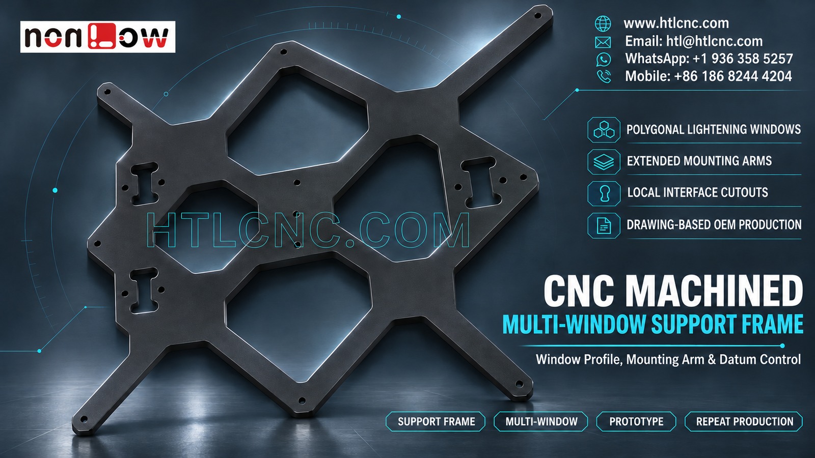
A CNC machined multi-window equipment support frame combines four polygonal openings, extended mounting arms, local interface cutouts and distributed holes that must remain coordinated through machining, finishing and repeat OEM inspection.
A CNC machined multi-window equipment support frame uses an open plate structure to connect several mounting regions while removing material from the central body. The selected photograph clearly shows one dark-finished frame with four large polygonal windows, four extended arms, three local keyhole-shaped interface cutouts and multiple drilled holes. Those visible features support a support-frame machining topic, but they do not prove the material, coating chemistry, load rating, equipment type or final application. HTL CNC provides drawing-based custom CNC machining for overseas OEMs, R&D companies, equipment builders, engineers and procurement teams from prototype review through repeat production.
Define the Load Path Before Quoting the Open Frame
The most important surfaces on an open frame are not always the largest ones. A buyer should identify which arm ends locate the assembly, which small holes receive fasteners or pins, which local cutouts engage mating hardware and which faces carry installation loads. A marked-up assembly view or simplified mating envelope helps the supplier understand those relationships without guessing the end use.
A complete RFQ should include the released 2D drawing, STEP model, exact material and condition, prototype quantity, forecast quantity, annual demand, finish, key tolerances, inspection records, packaging and destination. HTL's custom CNC machining service reviews stock route, workholding, cutter access, datum selection and measurement feasibility against that controlled package.
Treat the Four Polygonal Windows as One Profile Network
The four openings have straight segments, angled transitions and internal corners. Their individual dimensions matter, but so do the web widths between neighboring windows and the relationship of every opening to the outside frame. If each window is programmed or inspected from a convenient local edge, small position errors can accumulate and leave uneven webs or insufficient clearance for mating components.
The drawing should define profile tolerance, corner radii, minimum web widths, edge breaks and the datum system that controls the complete opening pattern. Depending on size and tolerance, inspection may combine CMM probing, optical profile measurement, calibrated templates or a customer-approved mating plate. The method should evaluate the four-window pattern as one coordinated feature set, not four unrelated pockets.
Hold Extended Mounting Arms to a Common Datum Structure
Four narrow arms project beyond the main body and terminate with visible holes. These arms can be sensitive to stock stress, clamping force, roughing sequence and finishing. Their true function is customer-defined, so the drawing should state arm-end position, hole size and location, face relationship, thickness, profile and any flatness or coplanarity requirement.
A stable process route can establish a primary face, two secondary references and a controlled coordinate system for all arm ends. Roughing may leave balanced stock before the final profile and hole operations. Free-state inspection after unclamping is important when the frame is thin enough to move, unless the customer specifies a restrained measurement condition.
Coordinate Local Interface Cutouts with Their Fastener Holes
Three keyhole-like cutouts are visible near the frame perimeter. Their exact mating function cannot be established from the image. The released design should define the cutout profile, orientation, depth or through condition, adjacent hole pattern, edge distance and permitted deburring. If a clip, bracket, pin or removable module engages the cutout, provide the mating geometry and required installation motion.
A profile can pass a local dimensional check while still being clocked incorrectly relative to the arm pattern. First-article reporting should therefore relate each local interface to the common frame datum. A customer-approved functional gauge can supplement CMM or optical results when installation direction and retention geometry matter.
Select Workholding That Supports the Thin Webs
Large openings reduce the amount of continuous material available for clamping. Unsupported webs may vibrate during contouring, and excessive fixture pressure can temporarily flatten or twist the part. The process plan should support broad stable regions, keep clamps away from finished edges and sequence roughing so internal stresses are released gradually.
Vacuum fixtures, fixture plates, tabs, sacrificial stock or dedicated nests may be considered according to material, part size, quantity and tolerance. No single method is appropriate for every frame. The supplier should also plan chip evacuation around the internal corners so recutting does not damage the visible finish or profile.
Use Machining Access, Not Marketing Labels, to Choose the Route
The visible geometry is dominated by planar milling, profile cutting and drilling, but the complete backside and any stepped features must be reviewed in CAD. Controlled 3-axis setups may be sufficient for a through-profile frame. Indexed or multi-axis access may be useful when local features approach from different directions or when fewer datum transfers improve the drawing-defined relationships.
HTL's 5-axis CNC machining capability is available when the actual model benefits from coordinated multi-face access; axis count is not a substitute for a sound fixture and inspection plan. Supplier qualification should focus on the proposed operation sequence, datum transfer, first-piece evidence and repeatability controls.
Separate Flatness, Coplanarity and Installed Fit
A broad skeletal frame can meet local thickness dimensions while still rocking on a fixture or pulling an arm out of plane. The buyer should distinguish overall flatness of a primary face, coplanarity among selected mounting pads or arm ends, parallelism between faces and final fit in the assembly. These are different characteristics and may require different measurement setups.
The drawing should state whether flatness is checked free-state, on three defined supports or in a customer-specified restraint fixture. If installation fasteners intentionally draw the frame into position, the allowed preload and tightening sequence belong in the assembly specification rather than being left to the machining supplier.
Specify the Dark Finish Without Assuming Its Process
The photographed frame has a dark surface appearance, but the image does not identify substrate or finishing chemistry. The purchase order should provide the exact material, finish standard, color and texture, coating thickness allowance, masking zones, electrical-contact areas, cosmetic class, rack-mark policy and certificate scope.
Window edges, arm-end holes and local interface cutouts may be affected by finish buildup. The drawing should say whether controlled dimensions apply before or after finishing. An approved color sample can define appearance, but it should accompany measurable requirements for fit and function.
Protect Narrow Arms During Deburring and Handling
Internal corners, polygonal window edges, small holes and local cutouts can retain burrs. Aggressive hand finishing may change an opening profile or round a locating edge, while insufficient deburring can interfere with assembly. Edge requirements should identify functional surfaces and allowed break size instead of relying only on a generic remove-sharp-edges note.
Handling and packaging also need attention because an impact at one long arm creates leverage at the central frame. Formed trays, nonabrasive separators or individual protective layers can keep arms from interlocking and prevent finished faces from rubbing during export transport.
Build First-Article Inspection Around Relationships
A useful first-article plan can report the primary face, overall envelope, four-window profile network, minimum web widths, arm-end positions, mounting-hole pattern, local interface cutout profiles and drawing-defined flatness or coplanarity. The report should identify part revision, finish condition, restraint method and measurement equipment.
Inspection may combine CMM results, optical comparison, height measurement, pins and customer-approved functional fixtures. A related guide to multi-opening interface panel machining discusses aperture-map and web control for another open-profile component.
Validate the Frame in Prototype Assembly
Prototype quantities let the customer's engineering team check arm-end alignment, window clearances, local interface engagement, fastener access, adjacent-component envelopes and installed flatness. Load, vibration, fatigue and environmental validation require customer-defined fixtures, cycles and pass criteria; none can be assigned from the photograph.
HTL's prototype and low-volume CNC machining service supports engineering samples and pilot lots before dedicated fixtures, inspection sampling and packaging are fixed. Any approved change to window shape, arm length, hole position, material or finish should update the 2D drawing and STEP model under the same revision.
Transfer the Approved Geometry into Repeat Production
Repeat orders depend on controlled material lots, fixture identification, CNC program revision, tool-life rules, first-piece approval, in-process profile checks and final inspection sampling. The datum route used for the accepted prototype should remain visible in setup instructions and reports.
Procurement teams should also state order cadence, annual demand, required inspection documents, export packaging and delivery destination. That information lets the supplier plan raw material, machine capacity, finishing and inspection without weakening revision control or drawing confidentiality.
RFQ Checklist for a Multi-Window Equipment Support Frame
Send the released 2D drawing and STEP file, simplified mating geometry, exact material and condition, prototype and production quantities, annual demand, functional datums, four-window profile requirements, arm-end and hole relationships, local interface definitions, free-state or restrained inspection condition, finish and masking notes, cosmetic standard, first-article scope, packaging and target delivery.
A complete package allows HTL CNC to quote the CNC machined multi-window equipment support frame as a controlled machining, finishing, inspection and delivery program rather than inferring load or application from appearance. For engineering review and quotation, visit www.htlcnc.com, email htl@htlcnc.com, send WhatsApp to +1 936 358 5257, or call mobile +86 186 8244 4204.
Have a part ready for engineering review?
Send your drawing, STEP file, material and quantity directly to HTL CNC for a manufacturing quotation.