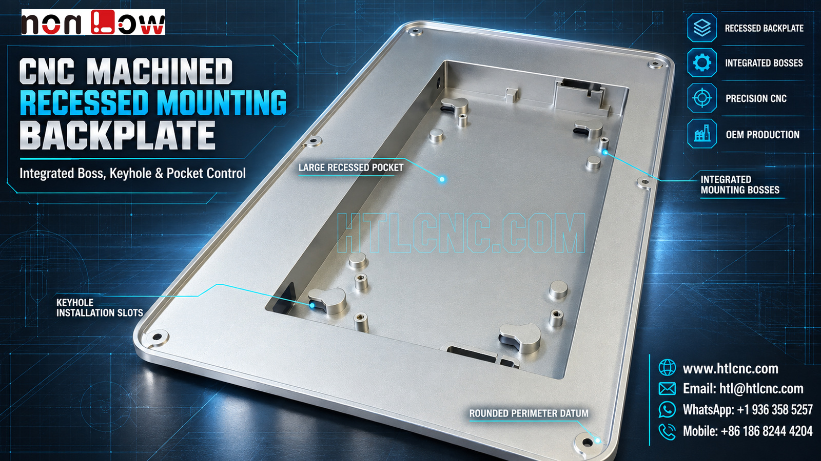
A CNC machined recessed mounting backplate combines a broad pocket, rounded perimeter, integrated bosses, keyhole slots and threaded posts that must remain coordinated for prototype fit and repeat OEM supply.
A CNC machined recessed mounting backplate combines a large rectangular pocket with a rounded outside perimeter, multiple raised mounting bosses, keyhole-shaped installation features, threaded posts and perimeter holes. The source photographs show these features clearly but do not establish the material grade, finish process, tolerance class, load rating or final equipment application. HTL CNC provides drawing-based custom CNC machining for overseas OEMs, equipment builders, product-development teams, engineers and procurement groups from prototype review through repeat production.
Start Supplier Review with the Backplate's Assembly Role
A broad recessed plate may support an internal module, cover, display assembly or another customer-defined structure, but the installed function cannot be confirmed from appearance. Before quotation, the buyer should identify the mating component, installed orientation, load path, cable or connector clearances, service access and which faces contact the final equipment.
The RFQ should include the released 2D drawing, complete STEP model, simplified mating-part envelopes, exact material and finish, prototype and production quantities, annual demand, inspection-document scope, packaging, destination and delivery target. HTL's custom CNC machining service uses that package to review stock form, workholding, cutting sequence and measurement access.
Define Functional Datums Before Large-Pocket Machining
The rounded perimeter, pocket floor, corner holes, bosses and keyhole slots need one controlled coordinate system. If the back face seats against a machine frame, it may be the primary datum; if the pocket locates an internal module, selected walls or boss centers may control secondary orientation. The released drawing must define the actual scheme.
Using only the outside profile as a shop reference may not prove that the internal mounting pattern aligns with the mating assembly. A first-article plan should reproduce the functional datums and state whether flatness and position are checked free-state, on specified supports or in an approved fixture.
Plan the Large Recessed Pocket Around Stability
Large recessed pocket machining removes material across most of the plate while leaving a wide perimeter frame. Toolpath direction, roughing allowance, clamp location, stock condition and thermal balance can influence the pocket floor and overall plate shape. The process route may use staged roughing, distributed material removal, supported finishing and unclamped verification according to the drawing.
The drawing should distinguish the functional pocket floor, ordinary clearance areas and cosmetic surfaces. Pocket depth, wall profile, internal corner radii, floor flatness and surface requirements should be specified only where assembly needs them. A general surface-finish note should not replace feature-specific acceptance criteria.
Inspect Integrated Mounting Bosses as a Common Plane
The visible pocket contains several cylindrical bosses and smaller threaded posts. Their function, diameter, height, bore, thread and positional tolerance must come from the controlled design. When several bosses support one module, checking each height independently does not prove that the group forms an acceptable mounting plane.
First-article inspection may combine height measurement, CMM probing, thread gauges and a customer-approved mating plate. The report should connect boss position and height to the same datums used for the pocket and perimeter, helping the buyer identify whether an assembly issue originates in the backplate, the mating part or fastener stack.
Treat Keyhole Features as Installation Interfaces
Several keyhole-shaped features are visible inside the recess. Their exact purpose is unknown, but a keyhole installation slot generally needs more than a simple diameter check. The released drawing should define the large entry diameter, narrow slot width, transition profile, orientation, edge condition and relationship to the mounting datum.
If a headed fastener or customer-supplied stud passes through the larger opening and translates into the narrow section, prototype validation should confirm insertion, travel, seating and removal without binding. Burrs, excessive edge break or finish buildup can change how the feature engages even when nominal dimensions appear acceptable.
Coordinate Threaded Posts and Perimeter Holes
Small threaded posts and perimeter holes may serve different components or assembly stages. A hole schedule should identify thread form, class, effective depth, counterbore or countersink condition, entry treatment and any no-go depth. Blind features require clear bottom and chip-control requirements.
Thread gauges confirm thread acceptance but not position, perpendicularity or common height. When perimeter holes register the backplate to an outer frame, their pattern should be inspected from the functional datums rather than from an unconstrained edge that may move after machining.
Control the Rounded Perimeter and Plate Edge
The outside frame has broad rounded corners and a continuous edge thickness. Overall length, width, corner profile, edge straightness and drawing-defined flatness can influence fit with a cover or surrounding enclosure. Deburring must remove sharp material without rolling the seating edge, enlarging corner holes or changing the intended perimeter profile.
Measurements taken only while the part is clamped may hide free-state movement. For large-format plate datum control, the drawing and quality plan should state the support condition, measurement sequence and whether a functional fixture is required for final acceptance.
Separate Visual Appearance from Material and Finish Facts
The photographed component has a light metallic appearance, but the image does not prove alloy, temper, anodizing, plating, blasting or another treatment. Purchase documents should state material standard and condition, approved alternates, finish process, color and texture limits, masking zones, cosmetic areas and certificate requirements.
Where coating or conversion layers affect keyhole engagement, threaded posts, boss fit or seating surfaces, the drawing should state whether dimensions apply before or after finishing. Approved appearance samples and defined viewing conditions can reduce subjective disputes across the broad visible frame.
Build Inspection Evidence Around Assembly Risk
A risk-based first-article report may cover outer profile, pocket size and depth, floor condition, boss positions and heights, keyhole geometry, threaded posts, perimeter-hole pattern and drawing-defined geometric controls. Measurement can combine calibrated hand tools, depth instruments, optical systems, thread gauges, CMM methods and functional masters according to feature access and tolerance.
The report should identify part number, revision, material and finish condition, datum setup, measurement equipment and any supported or free-state condition. Procurement teams should state the required documentation before quotation because full dimensional reporting, selected results and production sampling have different cost and schedule effects.
Validate the Prototype with Real Mating Hardware
Prototype parts should be trial-fitted with the intended module, headed fasteners, studs, screws, cover and surrounding frame. The engineering team can then verify pocket clearance, boss contact, keyhole insertion and slide travel, thread engagement, perimeter fit and tool access. Load, vibration or life performance requires customer-defined fixtures and pass criteria; none can be inferred from the photograph.
HTL's prototype and low-volume CNC machining service supports engineering samples and pilot lots before fixtures, programs and production sampling are locked. Approved changes should update the STEP model, 2D drawing, mating-part data and inspection plan under one revision.
Transfer the Approved Backplate into Repeat OEM Production
Repeat orders should control material source, CNC program revision, fixture identity, roughing and finishing sequence, tool-life limits, first-piece approval and sampling frequency. A design change affecting one boss, keyhole slot or pocket wall should identify the linked mating hardware so obsolete configurations are not mixed into a later shipment.
Packaging should prevent broad faces from rubbing and protect projecting bosses and threaded posts from impact. Protective film, clean separators, individual sleeves or formed trays may be selected according to finish and shipping route. Labels should show part number, revision, quantity and production lot for receiving traceability.
RFQ Checklist for a CNC Machined Recessed Mounting Backplate
Send the released 2D drawing and STEP file, assembly orientation, mating-part models, exact material and finish, prototype and repeat quantities, annual demand, functional datums, pocket requirements, boss and thread table, keyhole-slot definitions, perimeter and flatness controls, cosmetic zones, inspection-document scope, packaging, destination and target delivery. Confidential files can be reviewed under the buyer's document-control process.
This information allows HTL CNC to quote the CNC machined recessed mounting backplate as a coordinated pocket, boss, keyhole and datum-control program. For a related large frame with a central opening rather than a recessed floor, see our guide to CNC machined deep-wall equipment interface frame control.
Website: www.htlcnc.com Email: htl@htlcnc.com WhatsApp: +1 936 358 5257 Mobile: +86 186 8244 4204
Have a part ready for engineering review?
Send your drawing, STEP file, material and quantity directly to HTL CNC for a manufacturing quotation.