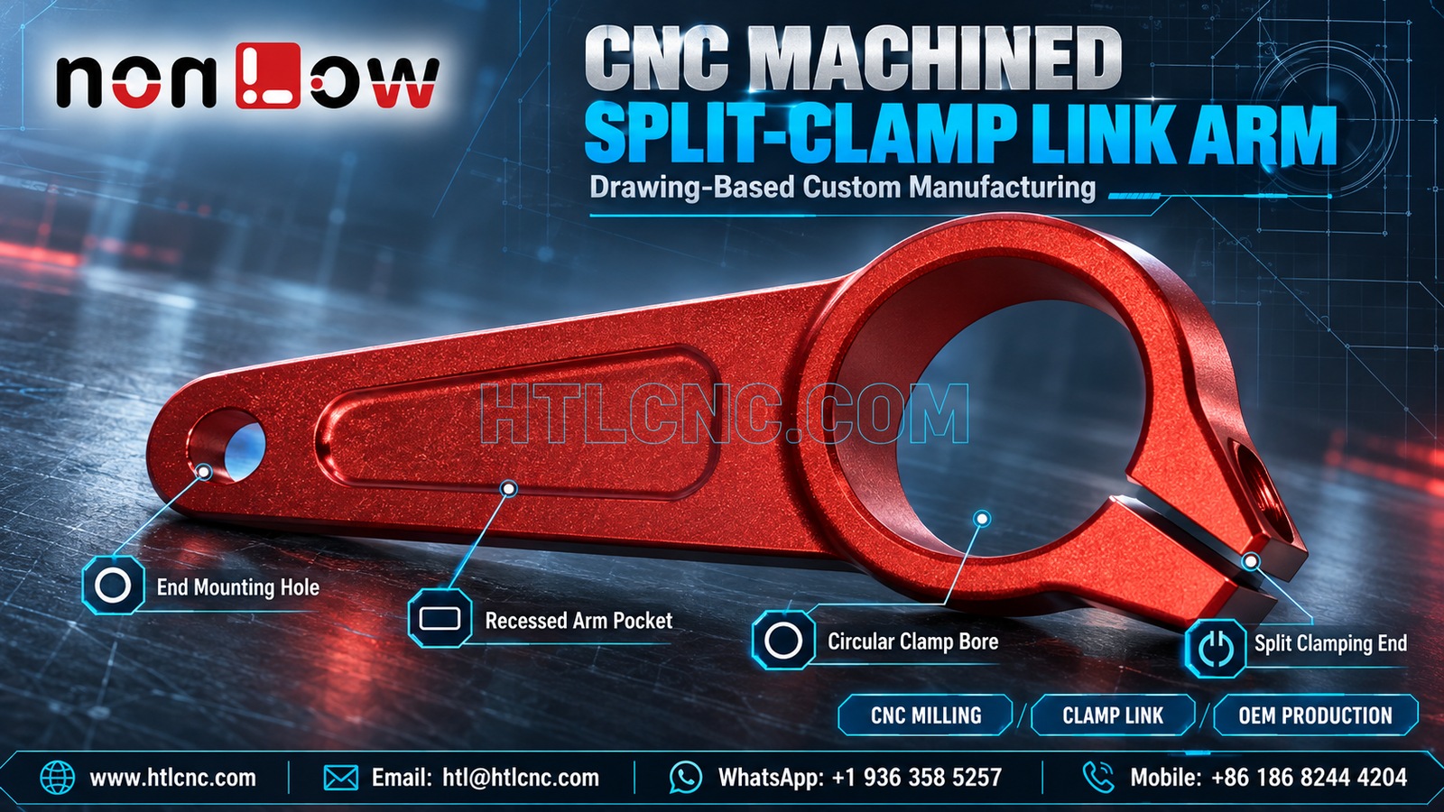
A CNC machined split-clamp link arm combines a circular clamp bore, open clamping end, recessed arm pocket and remote mounting hole that must remain coordinated through machining, finishing and inspection.
A CNC machined split-clamp link arm is a compact drawing-based component with several features that must work as one geometry. The selected photograph visibly shows a single red-finished arm with one large circular bore, a split opening at the clamping end, a long recessed pocket and one small through-hole at the opposite end. Those features support a split-clamp link-arm machining topic, but the image does not prove the material grade, clamped shaft size, fastening method, load, tolerance, finish process or final machine. HTL CNC supplies custom CNC machining for overseas OEMs, product-development companies, equipment builders, engineers and procurement teams from prototype review through repeat production.
What Must an RFQ Define for a Split-Clamp Link Arm?
The RFQ should identify the released 2D drawing and STEP file, exact material and condition, prototype and production quantities, annual demand, finish, critical dimensions, assembly datums, inspection records and delivery destination. Mating-shaft or tube data is especially useful because the large bore and split end appear to form one functional interface.
A photograph cannot establish the intended clamp force or fit. The buyer should define the mating diameter, required clearance or interference, slot condition, allowable distortion, tightening hardware and acceptance method. Supplier responsibility should be limited to drawing-defined manufacture unless the customer also supplies a validated clamp-force or assembly test.
Control the Circular Clamp Bore from a Stable Datum
The large bore dominates the part and is likely to influence alignment with the long arm, but its true function remains customer-defined. Its diameter, roundness, cylindricity, axis direction, edge breaks and position should reference stable drawing datums rather than the unfinished outside profile.
Because the bore is interrupted by the split, measurement can be sensitive to restraint. The drawing should state whether inspection occurs in a free state, with a specified gauge, or at a defined clamping condition. A bore gauge, CMM, air gauge or customer-approved functional master may be appropriate depending on tolerance and quantity.
Treat the Split End as a Flexible Feature, Not a Cosmetic Slot
The opening creates two jaws around the circular bore. Slot width alone does not describe their behavior. The drawing should define slot location, end condition, jaw thickness, parallelism or profile requirements, minimum edge distance and any hardware passage that belongs to the clamp interface.
Machining sequence matters because heavy roughing, residual stress, clamping pressure and finishing can change the free-state gap. If the part receives a coating or conversion finish, the buyer should also define whether bore and slot dimensions apply before or after finishing and whether any contact areas require masking.
Coordinate the Remote End Hole with the Bore Axis
A small through-hole is visible at the opposite end of the arm. It may be a pivot, fastener, locator or another interface; the photograph cannot confirm which. Diameter, positional tolerance, edge distance, perpendicularity and any counterbore or chamfer should therefore come from the released drawing.
The functional relationship may be the center-to-center distance between the large bore and the end hole, the angular orientation of the hole relative to the split, or both. This is a pattern-control problem rather than two unrelated diameter checks. A CMM or optical measurement system can report the complete relationship from one datum scheme.
Use the Recessed Arm Pocket as a Controlled Profile
The long face includes a shallow rounded-rectangle recess. It may reduce mass, create clearance, provide identification space or serve another purpose, but none of those functions can be assigned from the image. The drawing should specify pocket depth, wall transition, corner radii, floor condition and profile relative to the outside arm.
A thin remaining section can move during machining or finishing. Process planning should balance roughing stock, cutter engagement and fixture support so the pocket floor and outer arm do not distort. Cosmetic tool-path expectations should be separated from functional depth and profile requirements.
Select the Machining Route from Access and Quantity
The visible geometry is compatible with milling operations, but the starting blank and complete backside are not shown. Depending on material, stock route, tolerance and quantity, the component may use controlled 3-axis setups, indexed workholding, soft jaws or a dedicated fixture. More machine axes should only be selected when they reduce datum transfers or improve access.
HTL's custom CNC machining service reviews the model, drawing, mating interfaces and inspection scope before fixing the operation sequence. Prototype work can use flexible workholding, while repeat orders may justify dedicated locating features and in-process checks.
Plan Deburring Around the Slot and Interrupted Bore
The split end, bore edges, pocket transitions and small end hole can all retain sharp burrs. A generic edge-break note may be insufficient where the bore contacts a mating shaft or where the jaws flex during assembly. The drawing should identify functional edges, allowed break size and any edge that must remain sharp for a controlled reason.
Deburring should not widen the split, bell-mouth the bore or round the jaw tips. Visual inspection may be combined with magnification, tactile checks or approved edge standards. Cleaning requirements should identify prohibited chips, abrasive residue and oil where the component enters a sensitive assembly.
Specify the Red Finish Without Assuming Its Chemistry
The photograph shows a red surface appearance, but color alone does not confirm substrate or treatment. The RFQ should state the exact material, finish specification, color range, gloss or texture, cosmetic zones, masking areas, coating thickness allowance, corrosion requirement and certificate scope.
If anodizing or another dimensional finish is selected, bore size, slot gap and end-hole acceptance must account for the specified buildup. Buyers should also define whether contact marks from racking are allowed and where they may appear. A customer-approved color sample can prevent disagreements that numerical dimensions cannot resolve.
Build First-Article Inspection Around Relationships
A useful first-article report can include the outside envelope, primary face, large-bore size and axis, free-state split gap, jaw profile, recessed-pocket depth and profile, small-hole size and position, center-to-center relationship and drawing-defined geometric tolerances. The report should identify part revision, finish condition, restraint method and measurement equipment.
Inspection may combine CMM probing, bore and pin gauges, optical measurement, depth tools and a customer-approved mating master. Features that move under clamping should have an agreed inspection state before samples are produced. Gauge calibration and report format should be included in supplier qualification.
Validate Assembly During Prototype and Pilot Lots
Prototype quantities let the customer's engineering team check insertion over the mating feature, clamp closure, jaw clearance, link alignment, end-hole assembly, adjacent-component clearance and finish durability. Load, fatigue and clamp-force validation require customer-defined fixtures, cycles and pass criteria; they cannot be inferred from visual geometry.
HTL's prototype and low-volume CNC machining service supports sample and pilot-lot evaluation before fixtures, programs and inspection sampling are locked. Any approved change to the bore, slot, end hole, pocket, material or finish should update the 2D drawing and STEP model under the same revision.
Transfer the Approved Part into Repeat OEM Production
Repeat production depends on controlled material sources, fixture identification, CNC program revision, first-piece approval, tool-life limits, in-process measurement and final sampling. The bore-to-end-hole relationship and free-state split condition should remain tied to the same datum strategy used for the approved samples.
Packaging should prevent metal-to-metal contact on the colored finish and protect the thin split jaws from impact. Individual separators, formed trays or clean sleeves may be selected according to cosmetic sensitivity and shipping route. Labels should identify part number, revision, lot and quantity for receiving traceability.
RFQ Checklist for a CNC Machined Split-Clamp Link Arm
Send the released 2D drawing and STEP file, mating-component data, exact material and condition, prototype and production quantities, annual demand, bore and split requirements, end-hole relationship, pocket definition, free or restrained inspection state, finish specification, cosmetic standard, inspection-document scope, packaging, destination and target delivery. Confidential files can be reviewed under the buyer's required document-control process.
A complete RFQ allows HTL CNC to quote the CNC machined split-clamp link arm as a controlled machining and inspection program instead of estimating fit or load from a photograph. For a related elongated clamping geometry, review our guide to long open-frame CNC mounting arm datum control.
Website: www.htlcnc.com Email: htl@htlcnc.com WhatsApp: +1 936 358 5257 Mobile: +86 186 8244 4204
Have a part ready for engineering review?
Send your drawing, STEP file, material and quantity directly to HTL CNC for a manufacturing quotation.