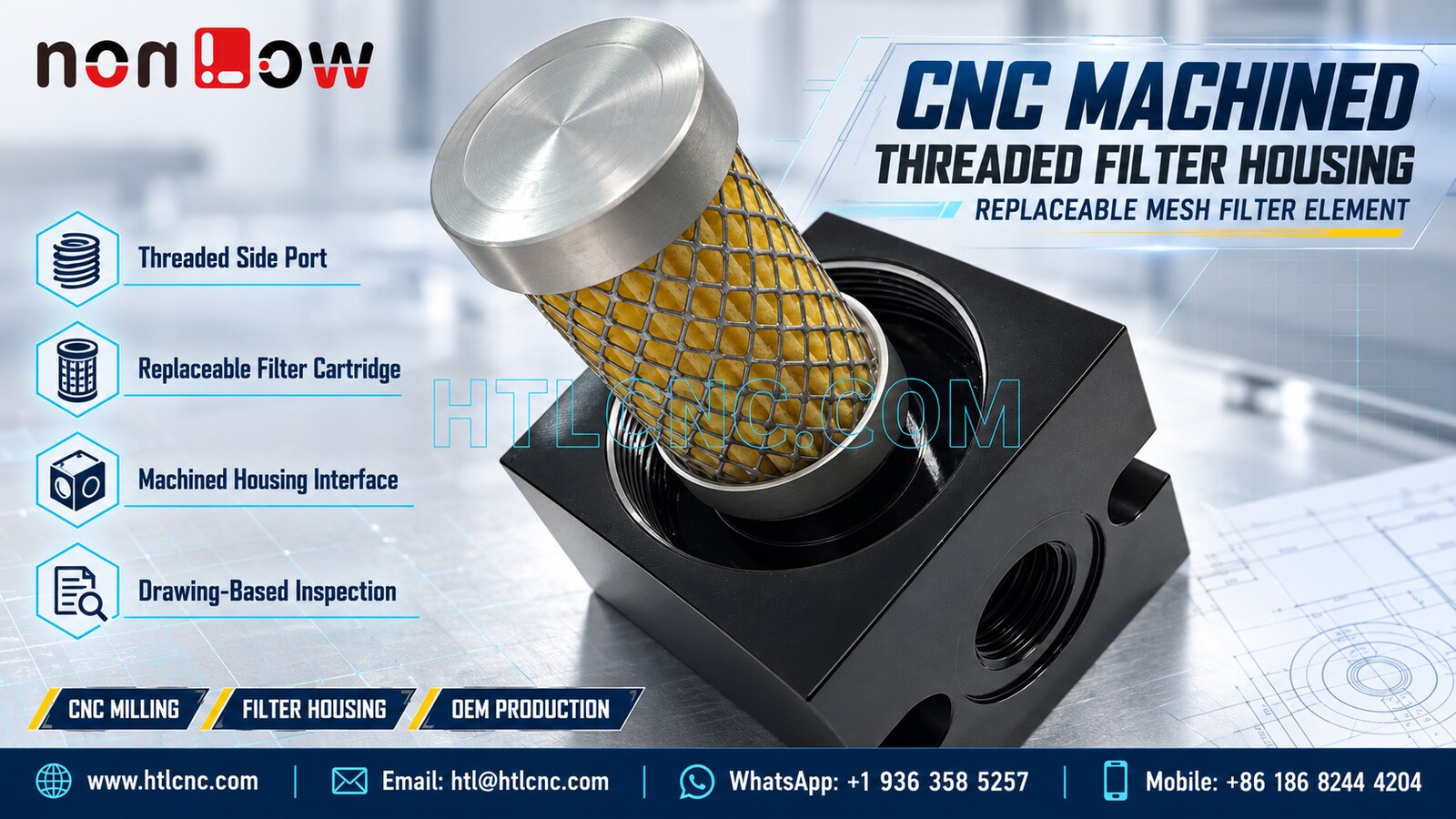
A CNC machined threaded filter housing combines a square multi-face body, a large cartridge seat, side-threaded connection and replaceable mesh element that require coordinated interface control.
A CNC machined threaded filter housing brings a machined body and a replaceable mesh element into one serviceable assembly. The selected photograph visibly shows one square dark-finished housing, a large threaded top recess, a cylindrical yellow porous element protected by diamond-pattern wire mesh, silver end hardware and a large threaded side opening. The image supports a filter-housing manufacturing topic, but it does not confirm the fluid or gas, filtration rating, material grades, thread standard, coating, pressure capability, flow direction or final machine. HTL CNC supplies drawing-based custom CNC machining for overseas OEMs, product-development teams, equipment builders, engineers and procurement groups from prototype sourcing through repeat production.
Define the Supplier Scope Before Requesting a Quote
A filter assembly combines parts that may come from different supply chains: the machined housing, threaded retainers, seals, porous media, support mesh and end hardware. The RFQ should state whether the supplier is responsible only for the housing, for selected machined interfaces, or for the complete assembled unit.
This boundary affects drawings, incoming inspection, functional testing and warranty responsibility. If the buyer supplies the element, HTL needs the controlled cartridge model and interface specification. If a complete assembly is requested, the buyer should identify approved media, seals, hardware and performance-test requirements rather than asking the machining supplier to infer them from a photograph.
Separate Filtration Performance from Machining Acceptance
Filter rating, pressure drop, chemical compatibility, temperature range and service life are system-level requirements. None can be established from the visible color or mesh pattern. The buyer must provide the working medium, particle-size target, cleanliness class, flow range, operating pressure, temperature, duty cycle and acceptance method.
Machining acceptance should separately cover drawing dimensions, threads, datums, surface condition and cartridge fit. Keeping these two scopes distinct allows the supplier to demonstrate what was manufactured while the customer's engineering team validates filtration performance under real operating conditions.
Control the Large Cartridge Seat and Top Thread
The housing visibly includes a large circular top recess with an internal thread or threaded retention feature. The drawing should define thread form, nominal size, class or tolerance, effective length, lead-in chamfer, relief, bottom condition and axial location from the primary mounting datum.
The cartridge seat may also include a shoulder, seal groove or pilot diameter that is not fully visible after assembly. These interfaces should be dimensioned from the released section view. Thread gauges alone do not verify shoulder depth, perpendicularity or the relationship between the cartridge axis and housing datum surfaces.
Coordinate the Side Port with the Cartridge Axis
A large threaded opening is visible on the housing side face. Its connection to the top cavity cannot be proven from the exterior image. The STEP model and section drawing should define the port axis, intersection, depth, thread engagement and any internal transition.
Depending on access and tolerance, the body may be produced through qualified 3-axis refixturing, indexed machining or 5-axis CNC machining. The process choice should preserve the positional relationship between the top cartridge seat, side port and mounting features without introducing unnecessary datum transfers.
Treat Cartridge Retention as a Service Interface
A replaceable element must be installed and removed without damaging threads, seals, mesh or adjacent components. The buyer should provide cartridge insertion depth, seating force, tightening method, tool clearance and acceptable end position. If a stop shoulder or cap controls compression, its stack-up should be evaluated with the actual seal and media hardware.
Prototype review should include repeated installation and removal. This can reveal cross-threading risk, insufficient wrench clearance, mesh contact, uneven seal compression or a cartridge that bottoms before its intended seat. Serviceability is not demonstrated by a one-time visual fit.
Specify the Mesh and Porous Element Independently
The visible element has an outer wire mesh around a porous yellow core. The image does not identify mesh alloy, wire diameter, opening size, media composition or filtration grade. Those details require a controlled element specification or an approved supplier part number.
The mesh supports and protects the media, but its ends, seam and retention method may affect assembly. Procurement documents should define allowable deformation, loose-wire limits, edge protection, cleanliness and whether the element is disposable, cleanable or reusable. Any media qualification remains separate from the CNC housing drawing.
Plan Deburring and Cleaning for Hidden Intersections
Threaded passages and intersecting cavities can retain chips, abrasive residue or finishing media. A generic clean-part note may not address the risk. The purchase specification should identify prohibited residue, flushing direction, drying method, inspection access and packaging cleanliness.
Deburring must remove loose material without rounding a seal shoulder, enlarging a port or damaging thread crests. Where the internal intersection is not directly visible, borescope inspection, controlled flushing, particle checks or another customer-approved method can be included in the manufacturing plan.
Verify Finish Requirements Without Assuming the Material
The dark housing and bright end hardware suggest different surface appearances, but the photograph does not prove material or treatment. The RFQ should state exact material standards, conditions, heat treatments, coatings, masking zones, corrosion requirements and certificate scope for each part.
Threads, cartridge pilots and sealing areas may need coating allowance or masking. Cosmetic requirements should be defined separately from functional dimensions, including approved color range, gloss, handling marks and inspection lighting when appearance matters.
Build a First-Article Report Around Assembly Interfaces
A risk-based first-article report can cover the outside envelope, mounting datum surfaces, top-thread size and axis, cartridge-seat diameter and depth, side-port thread and position, corner features, seal interfaces and drawing-defined geometric tolerances. The report should identify part revision, datum setup, measurement equipment and finish condition.
Measurement may combine CMM probing, thread gauges, depth tools, bore gauges, optical inspection and customer-approved functional masters. HTL's custom CNC machining service can align the inspection plan with the 2D drawing and STEP file before prototype release.
Validate the Complete Assembly During Prototype Builds
Prototype quantities should be used to check cartridge fit, thread engagement, seal seating, tool access, element removal, internal cleanliness and the customer's functional test. Flow, pressure, leakage and filtration tests require customer-defined fixtures, media and pass criteria.
HTL's prototype and low-volume CNC machining service supports sample and pilot-lot evaluation before repeat-production controls are locked. Any change to the cartridge, seal, thread, media or housing should update the corresponding drawings, approved-parts list and test specification under formal revision control.
Qualify Repeat Production and Export Packaging
Recurring supply depends on controlled material sources, machining programs, fixture identification, tool-life limits, first-piece approval, thread-gauge control, cleaning records and lot traceability. Housing and cartridge revisions should not be mixed during kitting or shipment.
Packaging should protect exposed threads, mesh and seal-contact surfaces. Thread caps, clean sleeves, individual separators or formed trays may be selected according to the cleanliness level and shipping route. Buyers should provide annual demand, release frequency, destination and target schedule so machining, element sourcing, assembly, inspection and export packing can be planned together.
RFQ Checklist for a Threaded Filter Housing Assembly
Send the released housing drawing, STEP file, cartridge and seal models, exact material and finish for each part, thread standards, prototype and production quantities, annual demand, functional datums, cartridge-seat and side-port requirements, media specification, cleaning standard, inspection-document scope, assembly responsibility, functional-test method, packaging, destination and target delivery. Confidential files can be reviewed under the buyer's required document-control process.
A complete RFQ lets HTL CNC quote the CNC machined threaded filter housing as a controlled interface and manufacturing program rather than estimating filtration performance from an image. For another threaded multi-face geometry, review our article on precision CNC threaded flange housing and side-port machining.
Website: www.htlcnc.com Email: htl@htlcnc.com WhatsApp: +1 936 358 5257 Mobile: +86 186 8244 4204
Have a part ready for engineering review?
Send your drawing, STEP file, material and quantity directly to HTL CNC for a manufacturing quotation.