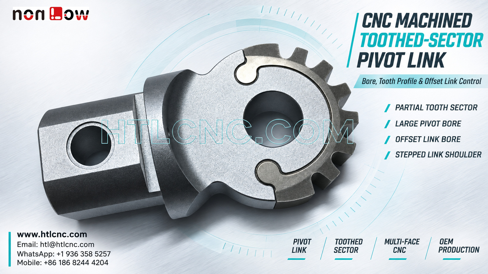
A CNC machined toothed-sector pivot link combines a large pivot bore, a partial external tooth profile, an offset link bore and stepped multi-face geometry that must stay coordinated for functional prototype validation and repeat OEM production.
A CNC machined toothed-sector pivot link combines a large circular pivot bore, a partial external tooth sector, an offset arm bore and stepped multi-face geometry in one compact component. The source photographs support those visible features, but they do not establish the final mechanism, material grade, heat treatment, coating, tolerance class or rated load. HTL CNC manufactures drawing-based custom parts for overseas OEMs, equipment builders, R&D companies, engineers and procurement teams, with engineering review from prototype qualification through repeat production.
Qualify the Part by Its Mating Interfaces
A toothed sector and two bores suggest a motion or positioning interface, but appearance alone cannot identify the customer's assembly. Supplier review should begin with the mating shaft or bushing, the component that engages the tooth sector, the installed orientation, the expected motion range and the load path. Those details help separate functional surfaces from ordinary clearance and cosmetic areas.
A useful RFQ includes the released 2D drawing, STEP model, simplified mating-part envelopes, exact material and finish requirements, prototype quantity, production forecast, annual demand, inspection-document needs, packaging method, destination and delivery target. HTL's custom CNC machining service uses this package to review stock form, fixturing, cutter access, datum transfer and inspection feasibility before quotation.
Establish the Main Pivot Bore as a Functional Datum
The large bore is the clearest rotational reference on the component. Its diameter, roundness, cylindricity, surface condition and relationship to the adjacent faces can affect shaft fit and motion. The drawing should state whether the bore runs directly on a shaft, receives a bushing or bearing, or provides general clearance. Each condition requires a different practical acceptance plan.
Bore size alone does not prove assembly performance. If the adjoining face locates against a shoulder, the drawing may also need perpendicularity or runout control between the bore axis and that seating face. Prototype inspection can combine calibrated bore measurement, CMM probing and a customer-approved mating gauge. Inspection results should be reported from the same datum structure used during machining rather than from an unrelated outside edge.
Control the Partial Tooth Sector from First Tooth to Last
A partial tooth profile creates different manufacturing questions from a full gear. The drawing must define the tooth form, pitch or module where applicable, pressure-angle basis, tooth count, sector angle, root and tip conditions, flank finish, end-tooth geometry and permitted edge treatment. None of those values can be determined reliably from a photograph.
The first and last teeth deserve special review because they transition into the non-toothed body. Tool approach, cutter exit and deburring must preserve the specified boundary without rolling an edge or changing the active flank. Depending on the controlled design, verification may use profile measurement, optical comparison, CMM scanning, span or pin methods, and a functional check with the customer's approved mating component. The measurement method should be agreed before production rather than inferred after parts are complete.
Hold the Offset Link Bore to the Pivot Coordinate System
The second bore sits on an offset rectangular arm. Its diameter may be important, but the center distance and angular relationship between the two bores often govern how a linkage assembles. The released drawing should define basic dimensions, positional tolerance, axis alignment and the face from which the offset is established.
When a shop measures the small bore from convenient outside surfaces, acceptable local dimensions can still produce an assembly error. A first-article report should relate both bore axes and the tooth sector to one functional coordinate system. For low-volume builds, a customer-supplied pin fixture or simplified mating assembly can add a direct fit check to dimensional inspection.
Plan Stepped Shoulders and Curved Face Details as One Setup Strategy
The visible part includes a raised circular region, stepped shoulder transitions and a curved segmented face detail. The photograph does not prove whether that curved boundary is an insert, relief, separate process feature or simply part of the customer's design, so its construction and acceptance must come from the CAD model and drawing.
These transitions influence cutter access, workholding and datum transfer. A process route may use indexed machining or another multi-face setup so the pivot bore, arm bore, tooth sector and shoulder faces remain coordinated. HTL can review such geometry through its 5-axis CNC machining capability when multi-direction access or controlled reorientation is genuinely useful; the final route depends on part size, tolerance, quantity and inspection requirements.
Define Side Features Without Over-Constraining the Design
Other source views show a small side-facing hole. Its function and thread status are not confirmed by the image. The controlled drawing should specify diameter or thread, depth, entry face, axis direction, edge break and position relative to the main bore or arm datum. If the side feature intersects another cavity, the buyer should also state requirements for breakthrough condition, internal burr removal and cleanliness.
This is a typical cross-face coordination issue: the hole can meet its own local size requirement while missing the intended internal location. Probe access, pin checks, borescope review or a section-specific gauge may be appropriate depending on the design.
Separate Material, Heat Treatment and Finish Decisions
The metallic appearance does not identify alloy or process. The RFQ should provide the exact material specification, condition, heat-treatment sequence, hardness range and coating or passivation standard. If teeth or bores require post-machining heat treatment, the manufacturing plan should account for distortion and specify whether finish machining or grinding follows treatment.
Finish buildup may alter bore fit, tooth engagement and shoulder seating. Drawings should distinguish masked surfaces, coated surfaces and areas that need final size after treatment. Material certificates, heat-treatment records and coating certificates can be included when required by the purchase order.
Build a First-Article Plan Around Functional Relationships
For a precision CNC part with multiple connected interfaces, a useful first-article inspection plan can include:
- main pivot bore size, form and axis; - offset link bore size, center distance and angular position; - tooth-sector profile, sector limits and end-tooth condition; - seating-face and shoulder relationships; - side-hole location and breakthrough condition where applicable; - edge condition, cleanliness and finish coverage; - mating-part or fixture checks defined by the customer.
The inspection report should identify the drawing revision, measurement method and datum setup. That traceability helps engineering and procurement teams compare supplier results without confusing fixture effects with part variation.
Use Prototype Builds to Retire Assembly Risk
Prototype machining is most valuable when the customer tests the part in its actual assembly. HTL can support prototype and low-volume CNC machining so teams can review shaft fit, linkage travel, tooth engagement, assembly access and service clearances before releasing a larger order. If the prototype changes, the next purchase order should reference the approved revision and record which inspection characteristics changed.
A controlled pilot batch can then confirm machining stability, inspection cycle, deburring method, finish handling and export packaging. For repeat production, documented setup references, tooling control, in-process checks and final inspection reduce variation between orders. Protective separation is especially important when external teeth and finished bore edges could contact adjacent parts during shipment.
Prepare a Complete RFQ for Repeat OEM Supply
For quotation, send HTL CNC the 2D drawing and STEP file, mating-interface information, material and heat-treatment standards, finish and masking notes, functional tolerances, prototype and annual quantities, required certificates, first-article format, packaging expectations and destination. If a similar linkage is being developed, the article on clevis-end shaft fork, hole and slot datum control offers another example of coordinating multiple mechanical interfaces from a common datum.
HTL CNC can review manufacturability, prototype strategy, inspection access and a repeat-production route while protecting customer drawing confidentiality. For an engineering and quotation review, visit www.htlcnc.com, email htl@htlcnc.com, send WhatsApp to +1 936 358 5257, or call mobile +86 186 8244 4204.
Have a part ready for engineering review?
Send your drawing, STEP file, material and quantity directly to HTL CNC for a manufacturing quotation.