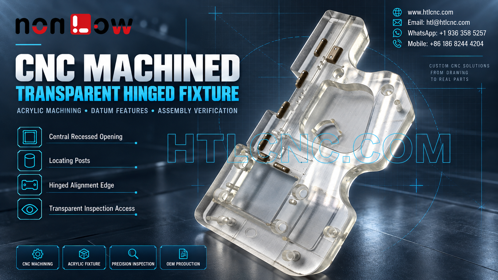
A CNC machined transparent acrylic hinged fixture combines clear inspection access, recessed locating geometry, multiple posts and a hinged alignment edge that must work together from a controlled datum plan.
A CNC machined transparent acrylic hinged fixture can make part location and visual access available in the same tool. The selected photographs visibly show one clear machined body with an irregular perimeter, a large central recessed opening, a lower rectangular recess, multiple locating posts and a row of small metal hinge or latch elements along one edge. The images do not establish the polymer grade, dimensional tolerances, mating component, inspection function or final industry. Those requirements must come from the buyer's released 2D drawing, 3D model and fixture specification. HTL CNC supports overseas OEMs, R&D companies, equipment builders, engineers and procurement teams with drawing-based acrylic machining, fixture components, prototype validation and repeat production.
Start the Fixture RFQ with Its Datum Logic
A fixture is useful only when it locates the customer's component in a repeatable and inspectable way. The drawing should identify the primary seating plane, the secondary locating feature and the tertiary feature that controls rotation. Recesses, posts, hinge elements and perimeter geometry can then be dimensioned from this common datum structure instead of from unrelated stock edges.
Buyers should send the mating-part model or a simplified interface model with the RFQ. That information helps the manufacturing team distinguish true locating features from clearance geometry and cosmetic surfaces. HTL's custom CNC machining service reviews released interface requirements before the fixture route, workholding and inspection plan are selected.
Control the Central Recess as a Functional Interface
The visible central opening has a recessed boundary and an internal shaped feature. A photograph cannot determine whether these surfaces locate, support, clear or inspect the mating component. The drawing should therefore define the profile, depth, corner radii, edge condition and positional relationship to the primary datum.
If the recess is functional, profile tolerance may be more informative than a chain of independent dimensions. The customer should also identify areas where tool-radius relief is permitted and surfaces that must remain free of chamfers. This prevents a supplier from making visually similar geometry that does not support the real assembly.
Define Locating Posts by Fit and Function
Several transparent cylindrical posts are visible around the plate. Their diameters, heights and center positions may influence insertion, support or alignment, but the images do not prove their exact purpose. Each post should have a complete size tolerance, positional requirement and relationship to the seating plane.
Where a post interfaces with a hole or slot, the RFQ should include the mating dimensions and required clearance. Procurement teams should state whether posts are machined integrally, bonded, pressed or assembled by another approved method. The manufacturing and inspection plan can then address height consistency, perpendicularity and the risk of damage during handling.
Keep the Hinged Alignment Edge in the Same Datum Chain
The row of small metal elements along one edge indicates a hinged or articulated relationship, but the image alone does not reveal its travel, preload or locking method. The released assembly drawing should identify pivot centers, fastener details, open and closed positions, required clearances and the feature that establishes the final aligned state.
Hinge mounting features should be controlled from the same datum framework as the recess and locating posts. If these features are produced or inspected from unrelated references, each item may pass individually while the completed fixture closes with an offset. A prototype build can confirm movement and final seating before repeat production is released.
Plan Acrylic Machining for Transparency and Edge Integrity
Clear polymer behaves differently from metal during milling and drilling. Tool sharpness, heat generation, chip evacuation, support and cutting sequence all influence edge quality and the risk of local whitening, melting or cracking. The correct parameters depend on the specified acrylic or other polymer grade, thickness, feature depth and surface requirement.
Protective film and handling rules should be defined early. If optical clarity is functional, the customer should specify which faces and edges require a controlled transparent finish and which machined tool marks are acceptable. General references to a clear appearance are not enough to establish measurable acceptance criteria.
Manage Thin Sections and Free-State Flatness
Pockets, recesses and perimeter cutouts reduce stiffness in the visible plate. Clamping force can temporarily flatten a part that changes shape after release, especially when material removal is unbalanced. Workholding should support stable zones without loading delicate posts or obstructing through-features.
A balanced roughing and finishing sequence may be required when flatness or profile is important. The drawing should state whether geometry is evaluated in a free state or under a defined restraint. It should also identify permissible bow, protected faces and any post-machining stress-relief or conditioning requirement.
Specify Surface Finish Without Guessing from the Photograph
The transparent appearance does not prove the exact resin grade, polishing method or optical standard. The RFQ should state material designation, color or tint, sheet or cast condition where relevant, required certificates, surface roughness or clarity criteria, edge finish, prohibited defects and cleaning method.
Machined, flame-polished, vapor-polished and manually polished surfaces can have different dimensional and cosmetic effects. No process should be selected solely from the photograph. Critical fits should remain tied to drawing dimensions after any approved finishing operation.
Build Inspection Around Assembly Risk
A risk-based first-article report may include the overall envelope, plate thickness, primary-plane flatness, central recess profile and depth, locating-post diameters and heights, post positions, hinge-hole coordinates, edge relationships and drawing-defined geometric tolerances. The exact list should follow the released fixture function rather than a generic checklist.
CMM inspection, height measurement, optical systems, calibrated pin or bore gauges and custom checking masters may be combined according to feature access and tolerance. Transparent surfaces can create optical-measurement challenges, so the supplier and buyer should agree on the measurement method and datum setup before production data is collected.
Use a Prototype to Verify Real Interaction
The first fixture should be evaluated with the actual mating component whenever possible. The engineering team can confirm insertion clearance, contact points, seating stability, access through the transparent body, hinge movement, closed-position alignment and safe removal. Any approved change should update the 2D drawing, 3D model and bill of materials under the same revision.
HTL's prototype and low-volume CNC machining service supports engineering samples and pilot quantities. After approval, locked CNC programs, qualified workholding, controlled assembly steps and first-piece checks help preserve the validated interface during repeat orders.
Prepare a Complete Overseas Sourcing Package
Send the released 2D drawing and STEP file, mating-part data, exact polymer specification, metal insert or hinge details, prototype and production quantities, annual demand, datum scheme, fit and profile requirements, surface and transparency criteria, inspection-document scope, packaging, destination and delivery target. If the fixture moves or closes, include the defined positions and acceptance test.
This information allows HTL CNC to quote the CNC machined transparent acrylic hinged fixture as a controlled manufacturing and verification program rather than guessing from appearance. Export packaging can then protect clear faces, machined edges, posts and assembled hardware during transit. Related sourcing teams can also review our guidance on precision CNC inspection fixture planning.
Website: www.htlcnc.com Email: htl@htlcnc.com WhatsApp: +1 936 358 5257 Mobile: +86 186 8244 4204
Have a part ready for engineering review?
Send your drawing, STEP file, material and quantity directly to HTL CNC for a manufacturing quotation.