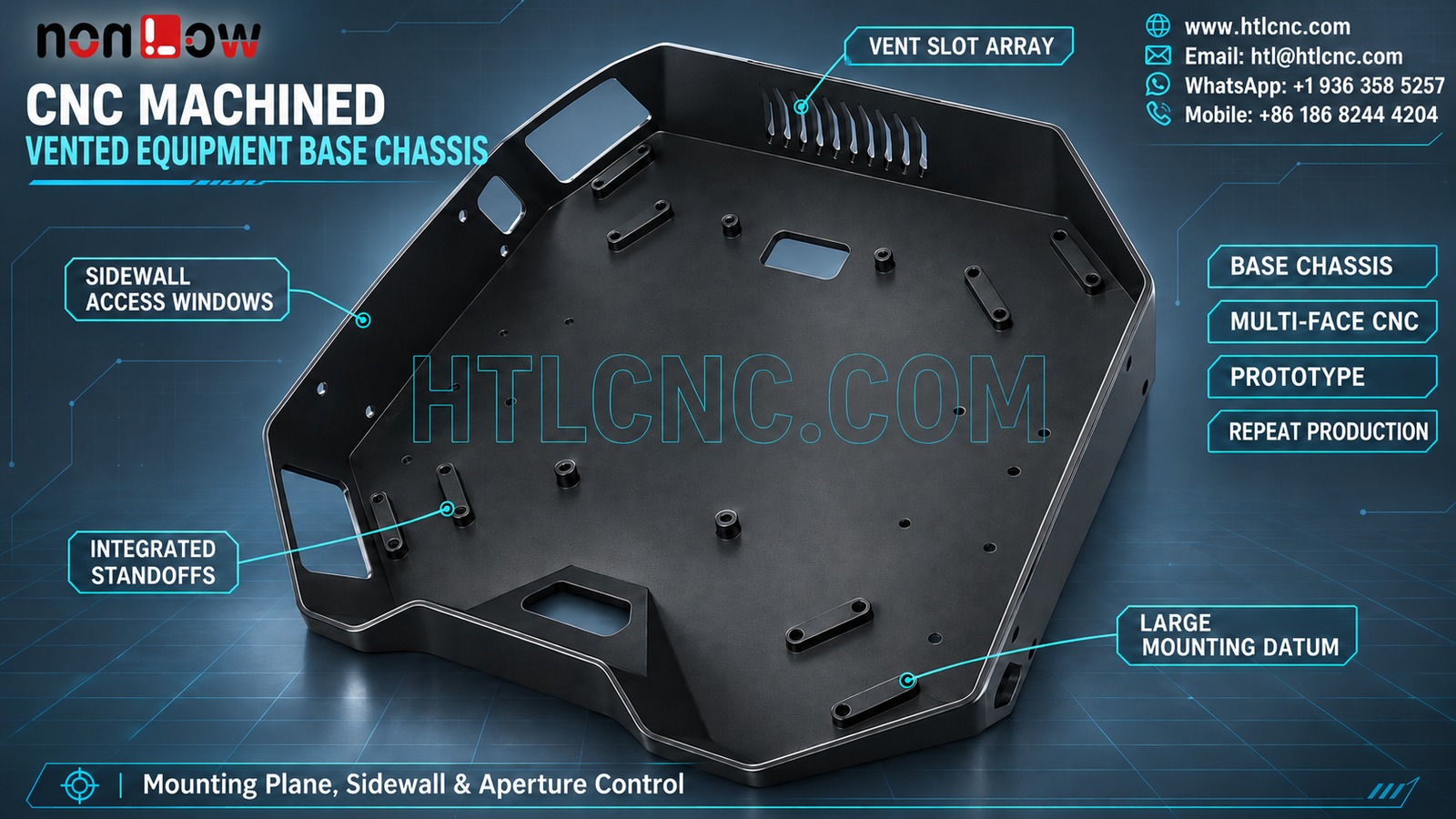
A CNC machined vented equipment base chassis combines a broad mounting plane, raised sidewalls, integrated standoffs, access windows, vent slots and distributed holes that must remain coordinated through prototype inspection and repeat OEM production.
A CNC machined vented equipment base chassis brings a large mounting plane, raised perimeter walls and multiple component interfaces into one structural tray. The selected photograph clearly shows a single black-finished base with integrated standoffs, distributed holes, several sidewall access windows, a central rectangular aperture and a grouped vent-slot array. Those visible features support a base-chassis machining topic, but they do not establish the material, coating chemistry, electronics, thermal duty, tolerance or final equipment. HTL CNC provides drawing-based custom CNC machining for overseas OEMs, equipment builders, product-development companies and procurement teams from prototype review through repeat supply.
Qualify the Chassis from the Assembly Map
A supplier needs more than the outside envelope. The engineering package should identify which standoffs support circuit boards or modules, which holes locate assemblies, which windows accept connectors or cables, and which sidewall faces mate with a cover. Simplified component envelopes and an interface map help distinguish functional features from ordinary clearance.
A complete RFQ includes the released 2D drawing, STEP model, exact material and condition, prototype and production quantities, annual demand, finish, inspection requirements, packaging and destination. HTL's custom CNC machining service uses that package to review stock route, setup sequence, tool access, datum transfer and measurement feasibility.
Establish the Large Mounting Plane Before the Small Features
The broad floor supports many local bosses and holes. If it is the primary assembly datum, the drawing should define its flatness, surface condition and relationship to the perimeter walls. The inspection condition also matters: a wide tray can measure differently free-state, on three supports or restrained in a fixture.
Machining plans should avoid using excessive clamp force to create a temporarily flat result. First-article reporting can identify support points, restraint method and measurement equipment so customer and supplier evaluate the same physical condition.
Coordinate Integrated Standoffs as Functional Height Groups
The visible floor contains cylindrical bosses and elongated two-hole standoffs. Their exact users are not confirmed by the image. The drawing should group features by mating module and define height, top-face condition, hole or thread, positional tolerance and relationship to the primary mounting plane.
Individual height checks do not prove that a board or bracket will sit correctly across several supports. CMM results, height measurement or a customer-approved fixture can evaluate each functional group. Mating hardware and driver access should also be reviewed before prototype release.
Treat Sidewall Windows as Cross-Face Interfaces
Several rectangular and shaped openings pass through the raised walls. Their size may be important, but position and clocking relative to the floor often govern connector or cable fit. The drawing should specify opening profile, corner radii, wall-face datum, edge treatment and permitted finish buildup.
Cross-face features can satisfy local dimensions while missing a neighboring module because of datum-transfer error. A stable process may use indexed workholding, qualified secondary setups or coordinated multi-axis access depending on complete geometry and tolerance. HTL's 5-axis CNC machining capability can be reviewed when multi-direction access genuinely reduces setups; axis count alone is not a quality claim.
Define the Vent-Slot Array without Assuming Thermal Performance
The upper wall shows a repeated slot array. The photograph confirms ventilation-style geometry but does not prove airflow, fan direction, heat load or required cooling. The buyer should define slot width, spacing, end radius, profile location, minimum web, edge condition and any applicable safety or ingress requirement.
Machining and deburring must preserve the narrow webs between slots. If airflow or acoustic performance matters, the customer should provide a validated test setup and pass criteria. Dimensional acceptance does not substitute for thermal, airflow or noise testing.
Hold the Perimeter Walls and Cover Interface Together
Raised sidewalls can influence cover fit, seam appearance and internal clearance. The drawing should identify wall height, wall profile, corner transitions, top-edge relationship and any controlled cover or gasket interface. If a separate cover attaches to the sidewalls, provide its model and fastener pattern.
Wall height at one point does not prove coplanarity around the perimeter. A first-article plan may need several height locations, top-edge profile and the relationship of side holes to the mounting plane. Fixture design should support the floor without distorting the walls.
Plan Thin-Wall Machining for Stability
Large floors and raised walls can move as stock is removed. Tool pressure, heat and unbalanced roughing may affect floor flatness or wall position. A practical route can use balanced material removal, staged roughing, stress-relief steps where specified, controlled semifinish stock and free-state checks between operations.
The actual route depends on material, stock form, wall thickness, tolerance and quantity. Buyers should avoid prescribing a machine axis count without sharing functional datums and inspection needs. Supplier qualification is stronger when it reviews the proposed fixture and measurement plan.
Separate Black Appearance from Finish Specification
The source part has a dark surface, but appearance cannot identify the substrate or treatment. The purchase order should state material, finish standard, color and texture, coating allowance, masking zones, cosmetic areas, rack-contact policy and certificate scope.
Standoff threads, locating holes, cover interfaces and connector windows may require different protection. If the finish changes a controlled fit, the drawing should state whether dimensions apply before or after treatment and whether post-finish inspection is required.
Build Inspection around Interface Families
A useful first-article report can organize results by the primary mounting plane, standoff groups, floor hole patterns, perimeter wall geometry, sidewall apertures and vent-slot array. That structure is easier for an OEM team to review than a list arranged only by machining operation.
Inspection may combine CMM probing, height measurement, pins, thread gauges, optical profile inspection and customer-approved mating fixtures. A related guide to multi-port equipment enclosure machining covers additional side-opening and fastener-pattern issues for enclosure-style components.
Validate the Prototype in the Intended Assembly Order
Prototype evaluation should install the base on its supports, place the main internal modules on the standoffs, route connector or cable interfaces through the wall openings, then fit the cover. This sequence checks mounting height, hole alignment, side access, tool clearance and closure before production quantities are released.
Load, vibration, thermal, airflow, ingress and electromagnetic tests require customer-defined equipment and acceptance criteria. HTL's prototype and low-volume CNC machining service supports engineering samples and pilot lots before fixtures, gauges and sampling plans are fixed.
Transfer Approved Geometry into Repeat OEM Supply
After prototype approval, controlled raw material, fixture identification, CNC program revision, first-piece checks, tool-life rules and final sampling support repeat-order consistency. Any change to standoff height, side opening, vent geometry, cover interface, material or finish should update the 2D drawing and STEP model under the same revision.
Packaging should prevent the broad floor, wall edges and black cosmetic surfaces from rubbing against other parts. Formed trays, nonabrasive separators or individual sleeves can be selected for the finish and export route. Labels should link part number, revision, lot and quantity to inspection records.
RFQ Checklist for a Vented Equipment Base Chassis
Send the released 2D drawing and STEP file, assembly/interface map, exact material and condition, prototype and production quantities, annual demand, mounting-plane requirement, standoff groups, complete hole and thread schedule, sidewall opening profiles, vent-slot definition, cover interface, finish and masking notes, first-article scope, packaging, destination and delivery target.
A complete package allows HTL CNC to quote the CNC machined vented equipment base chassis as a controlled multi-face machining, finishing, inspection and delivery program rather than guessing electronics or thermal performance from the photograph. For engineering review and quotation, visit www.htlcnc.com, email htl@htlcnc.com, send WhatsApp to +1 936 358 5257, or call mobile +86 186 8244 4204.
Have a part ready for engineering review?
Send your drawing, STEP file, material and quantity directly to HTL CNC for a manufacturing quotation.