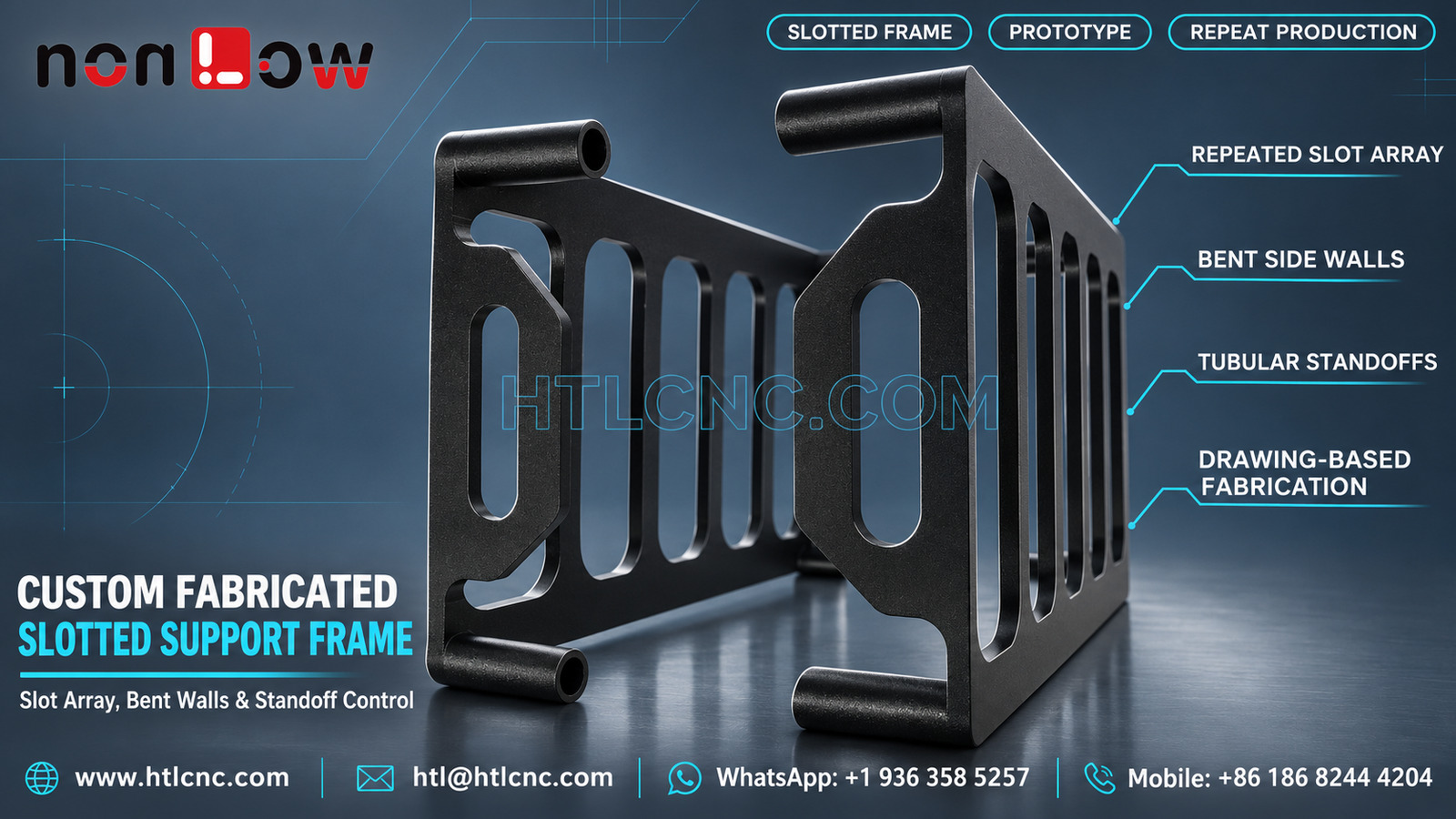
A custom fabricated slotted support frame combines repeated rounded openings, bent plate walls, end windows and tubular standoffs that require one coordinated datum, joining and inspection plan.
A custom fabricated slotted support frame combines repeated rounded rectangular openings, bent plate walls, large end windows, a local mounting tab and four tubular standoffs in one lightweight structure. The photograph supports those visible facts, but it does not identify the material, cutting process, joining method, black finish, tolerances, load rating or final equipment. HTL CNC reviews drawing-based fabricated and machined assemblies for overseas OEMs, engineering teams and procurement organizations from prototype qualification through repeat production.
Begin the RFQ with the Supported Envelope
The buyer should identify what sits inside or against the frame, which end controls location, what the tubular features contact and whether any slots provide ventilation, access, adjustment or weight reduction. A simplified mating envelope and keep-out model help the supplier understand assembly function without requiring unrelated system disclosure.
A complete RFQ includes the released 2D drawing, STEP model, exact material and thickness, prototype and production quantities, annual demand, surface finish, joining requirements, inspection documents, packaging and destination. HTL's custom CNC machining service can coordinate machined interfaces with drawing-based fabricated structures when the project genuinely requires both.
Define the Primary Datum before Slot Production
The broad plate surfaces and end edges offer several possible references, but the manufacturing datum should follow assembly function. The drawing should identify the primary seating plane, the end or centerline that controls length and the feature that prevents rotation or lateral shift.
The repeated slot pattern, bent walls and standoffs can then be related to one coordinate system. Without a shared datum, individual features may pass local dimensions while the complete frame fails to align with the supported assembly.
Control Repeated Rounded Slots as a Pattern
The frame contains multiple elongated openings with rounded ends. The drawing should define slot count, width, length, corner radius, pitch, edge distance and any intentional differences between rows or walls. A typical-feature note can reduce clutter only when every exception is clearly identified.
Depending on confirmed material and thickness, the openings may be produced by laser cutting, waterjet, punching, routing, milling or another approved process. The photograph cannot prove which route was used. Cut-edge condition, taper, dross, heat effect and burr limits should follow the purchase specification.
Maintain Wall Geometry through Bending
The visible frame has plate walls meeting at controlled angles. Bend allowance, inside radius, neutral-axis assumptions, grain direction where relevant and springback compensation should be established from the real material and thickness. Flat-pattern dimensions alone are not sufficient acceptance criteria for the finished structure.
Inspection should verify wall angle, spacing and squareness in the free state or in a customer-defined restraint. Excessive fixturing force can temporarily force a frame into tolerance and allow it to move after release.
Locate the Tubular Standoffs from the Functional Plane
Four tubular features project from the frame corners. Their exact role and attachment method cannot be inferred from the image. The drawing should state outside and inside diameters, projection length, end condition, axis orientation and positional relationship to the frame datums.
If the tubes are joined to plate, the supplier needs a defined weld, braze, fastener, interference or other approved method. Joint size, penetration, cosmetic limits and distortion controls must be specified when relevant; a visual photograph is not a joining standard.
Coordinate End Windows and Mounting Tabs
Large openings in the end walls and a smaller tab or slot may interact with cables, fasteners or mating hardware, but their purpose is unverified. The drawing should identify critical clearances, hole or slot dimensions, local edge breaks and required access zones.
Prototype inspection should compare these features to the supported envelope rather than measuring each opening in isolation. A checking fixture or mating sample can reveal cumulative effects from slot position, bend angle and standoff location.
Plan Cutting, Forming and Joining as One Sequence
The best process depends on material, thickness, lot size, cosmetic requirement and joint design. A practical route may establish the flat pattern, cut the openings, form the walls, add tubes or secondary parts, correct controlled distortion and complete the approved finish.
Features close to bends require special review because forming can distort slot ends or reduce edge distance. Joining after bending may pull walls out of square. The supplier should reserve final inspection for the assembled free-state frame, not only for separate flat components.
Separate Black Appearance from Finish Specification
The image confirms a dark surface but cannot identify powder coating, paint, anodizing, plating, oxide, polymer or another treatment. The purchase order should state the substrate, finish standard, color and texture, masking zones, coating allowance, rack-contact policy, certificates and cosmetic acceptance.
Slot edges, tube bores, seating faces and threads or holes—if any—may need different masking or post-finish checks. Packaging material should be compatible with the approved finish and should not leave impressions or residue.
Build First-Article Inspection around Assembly Risk
A useful first-article report can cover overall envelope, primary datum plane, wall spacing and angle, repeated slot pattern, end-window geometry, tubular standoff positions and projections, joining condition, edge quality and drawing-defined geometric tolerances. It should identify revision, free or restrained state, fixture, measurement equipment and gauge IDs.
A related article on vented equipment base chassis control discusses additional slot-array, sidewall and mounting-datum considerations for open equipment structures.
Use Prototype Builds to Confirm Fit and Access
Prototype validation should place the intended component or approved envelope inside the frame, confirm seating and wall clearance, check access through the slots and end windows, and verify contact at all four standoffs. If load, vibration or thermal testing is required, the customer must define the fixture, orientation, cycle and acceptance criteria.
HTL's prototype and low-volume CNC machining service supports engineering samples and pilot quantities for projects that combine fabricated structures with machined interfaces. Approved corrections should update the drawing and model under one controlled revision.
Transfer the Approved Frame into Repeat Supply
Repeat-order consistency depends on controlled material and thickness, flat-pattern revision, forming tools, joining fixtures, process parameters, first-piece approval, finish-lot control and formal change management. Sharing annual demand and batch size helps the supplier plan stock, fixtures, inspection capacity and delivery cadence.
Export packaging should support the structure without loading projecting tubes or rubbing black surfaces. Formed separators or individual wrapping can prevent frame-to-frame contact. Labels should link part number, revision, quantity and lot to inspection records.
RFQ Checklist for a Slotted Support Frame
Send the released drawing and STEP file, supported envelope, exact material and thickness, approved cutting and joining requirements, datum scheme, slot pattern, bend details, tubular standoff definition, finish and masking notes, prototype and production quantities, annual demand, tolerances, inspection-document scope, packaging, destination and delivery target.
This package allows HTL CNC to quote the custom fabricated slotted support frame as a controlled manufacturing and inspection program rather than estimating material, joining, coating or function from a photograph. For engineering review and quotation, visit www.htlcnc.com, email htl@htlcnc.com, send WhatsApp to +1 936 358 5257, or call mobile +86 186 8244 4204.
Have a part ready for engineering review?
Send your drawing, STEP file, material and quantity directly to HTL CNC for a manufacturing quotation.