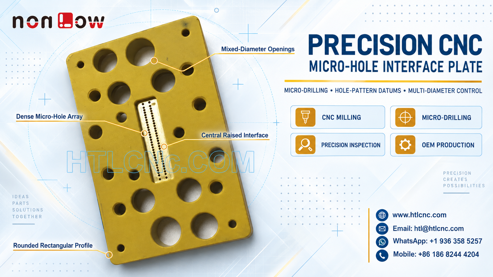
A precision CNC micro-hole interface plate combines a dense micro-hole array, mixed-diameter openings, a central raised interface and rounded outer geometry that must be controlled from a coherent datum system.
A precision CNC micro-hole interface plate can place very different feature scales on one compact component. The selected product photograph visibly shows a rounded rectangular plate, mixed-diameter through-openings and a central raised rectangular interface containing two dense rows of small holes. The image does not prove the material grade, surface treatment, dimensional tolerances, hole function or final application. Those requirements must come from the buyer's released drawing, 3D model and assembly specification. HTL CNC supports overseas OEMs, R&D teams, equipment builders, engineers and sourcing professionals with drawing-based CNC milling, micro-hole array machining, prototype validation and repeat production.
Qualify the Supplier Against the Functional Datum Scheme
A plate with many openings is not simply a collection of independent hole sizes. The customer drawing should identify the primary mounting face, secondary edge or centerline, and tertiary clocking feature used to locate the complete pattern. Critical dimensions should originate from these functional datums rather than from convenient raw-stock edges.
This datum hierarchy guides fixture design, CNC programming and final inspection. HTL's custom CNC machining service reviews hole coordinates, feature relationships and access before the process route is released. When the plate mates with connectors, pins, valves, nozzles or another patterned component, the mating-part data should accompany the RFQ.
Separate the Micro-Hole Array from General Drilled Features
The central interface visibly contains two narrow rows of small openings. A photograph cannot establish their diameter, depth, pitch, breakthrough condition or acceptance criteria. The released drawing should state each value explicitly and distinguish true micro-drilled features from larger clearance, fastening or locating holes.
Micro drilling is sensitive to tool runout, unsupported tool length, entry condition, chip evacuation and accumulated wear. A supplier qualification plan may therefore include a short process trial, magnified edge review, tool-life limits and periodic checks within the array. The correct method depends on the specified diameter, aspect ratio, material and production quantity.
Hold the Mixed-Diameter Pattern to One Coordinate System
The visible plate includes large and small circular openings distributed around the central land. If these features are programmed or inspected from unrelated references, local size may pass while the assembled pattern does not align. A common coordinate system helps control true position, pitch and orientation across the full part.
The drawing should identify which openings are functional locators, which are clearance features and which need only general positional control. Basic dimensions, datum references and position tolerances are usually clearer than long chained dimensions when assembly depends on a complete hole pattern.
Protect the Central Raised Interface
The micro-hole rows sit within a visibly raised rectangular region. That area may require separate control of height, flatness, parallelism, edge condition and relation to the main plate face, but its actual function cannot be inferred from the image. The buyer should define whether it is a seating surface, protected interface or nonfunctional relief.
Fixture clamps and probing points should avoid damaging this region. Machining strategy may establish the broad mounting face first, rough surrounding material while the part remains supported, then finish the raised land and hole array from a stable datum condition.
Plan Workholding for a Perforated Plate
A plate containing many large openings has less continuous support than solid stock. Cutting forces, residual stress and clamping pressure can influence flatness as material is removed. Workholding should distribute support without covering through-features or distorting the central interface.
Depending on size and tolerance, the route may use a sacrificial subplate, vacuum support, soft jaws, dedicated fixture points or another qualified method. The released model must include all hidden pockets, counterbores, steps and backside details because these can change support and setup sequence.
Define Edge Quality at Every Scale
Large bores, small holes and micro-holes need different edge-control methods. Aggressive deburring that is acceptable on a general clearance opening may damage the exit edge or diameter of a very small drilled feature. The drawing should identify permitted chamfers, burr limits, protected sealing or seating surfaces and any holes that must remain sharp within a controlled limit.
Cleaning is equally important. Chips or media retained in small passages can obstruct inspection and later assembly. The required cleanliness method, prohibited residues and packaging environment should be stated when they are functionally significant.
Build a Layered First-Article Inspection Plan
A practical first-article report can divide the part into four groups: overall profile and thickness, large openings, smaller general holes, and the dense central micro-hole array. This makes it easier to assign suitable measurement methods and sampling rules to each risk.
Calibrated micrometers, pin gauges, bore gauges, optical measurement, video metrology and CMM inspection may be combined according to tolerance and feature access. A buyer requesting full array reporting should define whether every hole requires size and position results or whether an approved sampling plan is acceptable.
Do Not Specify Material or Finish from Color
The gold appearance in the photograph does not establish aluminum, copper alloy, anodizing, conversion coating or any other material or treatment. The RFQ should provide the exact material standard and condition, heat treatment if applicable, surface finish, coating thickness, masking zones, cosmetic criteria and certificate requirements.
If finishing can affect hole size or interface height, the drawing should state whether dimensions apply before or after treatment. Test coupons or first-off samples may be useful when the finish supplier must validate coverage around small openings.
Use Prototypes to Confirm Assembly Evidence
A prototype batch gives the engineering team an opportunity to confirm hole-pattern alignment, mating clearance, seating on the raised interface, edge condition and inspection access with the real assembly. Any approved change should update the 2D drawing and STEP file under the same revision before the pilot lot begins.
HTL's prototype and low-volume CNC machining service supports engineering samples and staged releases. After approval, locked programs, qualified fixtures, documented tool-change intervals and first-piece verification help transfer the process into repeat supply.
Prepare an RFQ That Supports a Reliable Quote
Send the released 2D drawing and STEP file, exact material and finish, prototype and production quantities, annual demand, datum scheme, critical hole schedule, micro-hole diameter and depth, positional requirements, raised-interface controls, deburring and cleanliness criteria, inspection-document scope, packaging, destination and target schedule. If the plate mates with another patterned component, include the assembly model or interface drawing.
With this information, HTL CNC can prepare a controlled manufacturing and inspection plan for the precision CNC micro-hole interface plate without guessing from appearance. Related work on complex patterned components can also be reviewed through our article on CNC interface panel datum control.
Website: www.htlcnc.com Email: htl@htlcnc.com WhatsApp: +1 936 358 5257 Mobile: +86 186 8244 4204
Have a part ready for engineering review?
Send your drawing, STEP file, material and quantity directly to HTL CNC for a manufacturing quotation.