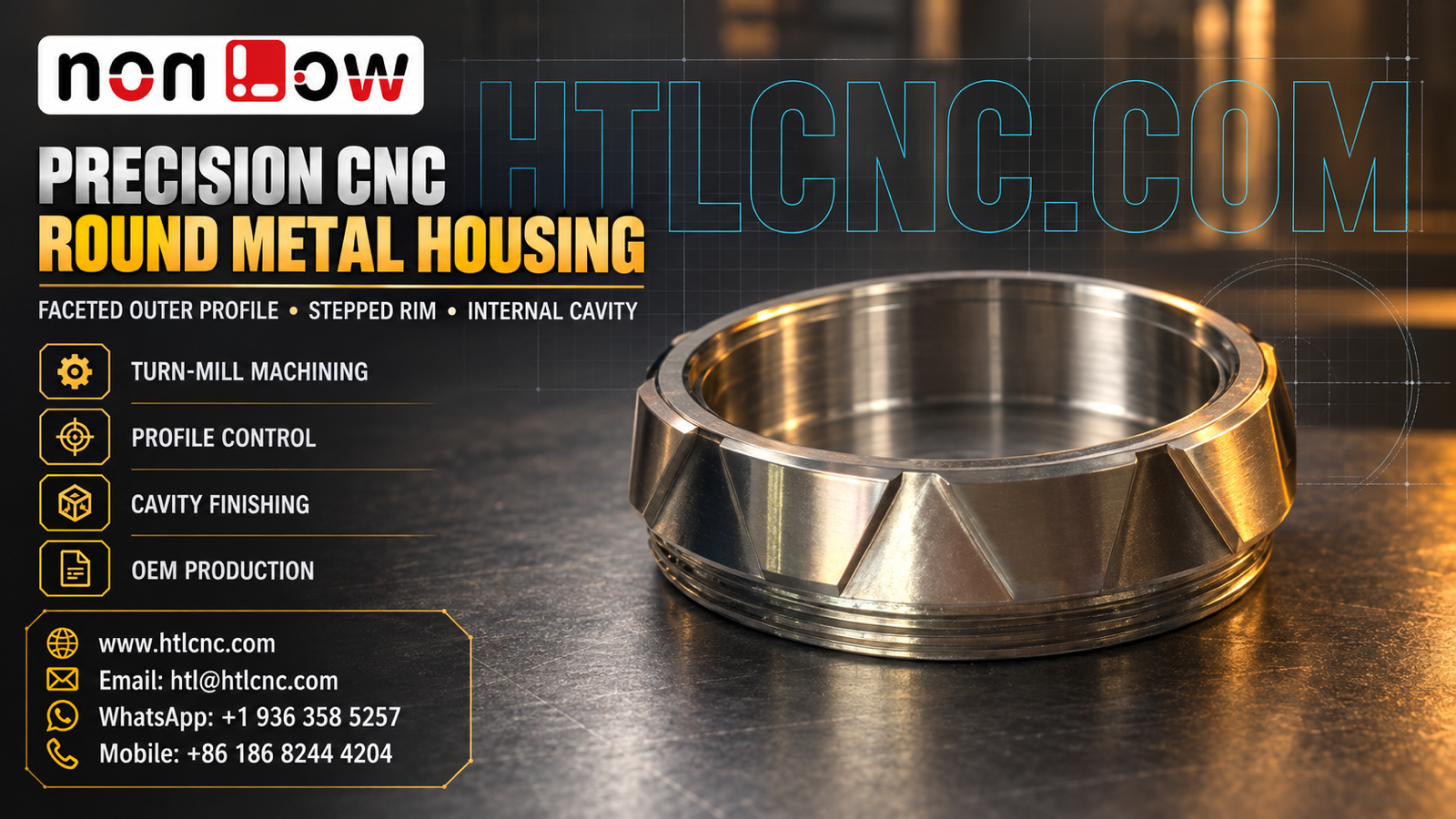
A precision CNC round metal housing combines a circular internal cavity, stepped rim, faceted outside profile and fine edge transitions that must remain coordinated through turn-mill machining and inspection.
A precision CNC round metal housing can look rotationally simple while concentrating several sourcing risks into one compact component. The selected photographs visibly show a shallow circular body with an open internal cavity, a stepped upper rim, a repeating faceted or scalloped outside profile and narrow circumferential features near the lower edge. The source also contains decorative engraving, but those markings were removed from the poster and are not used to infer a final application. The images do not establish material grade, exact tolerances, finish specification, thread standard, sealing duty or end use. HTL CNC manufactures drawing-based custom components for overseas OEMs, R&D teams, equipment builders, engineers and procurement groups from prototype review through repeat production.
Why a Round Housing May Need Both Turning and Milling
The cavity, rim and circumferential steps are naturally referenced to a common rotational axis. The faceted outside surface, however, interrupts that symmetry. A qualified process may therefore combine CNC turning for coaxial surfaces with indexed milling or turn-mill machining for the repeated exterior profile. The final route depends on the released model, tolerance relationships, material, quantity and inspection plan.
Machine selection should reduce uncertain datum transfers rather than add complexity for its own sake. HTL's CNC turning and turn-mill machining service reviews whether critical diameters and milled faces can remain referenced to one stable axis and seating face.
Establish the Functional Axis and Seating Face First
A complete RFQ should identify the axis that controls the internal cavity and circular rim, plus the face that establishes axial location in assembly. Raw-stock surfaces or cosmetic outside facets should not become default datums if the actual component seats from a machined shoulder or circular register.
The drawing should state which diameters are coaxial, which face controls perpendicularity and how the outside profile is clocked. This datum scheme helps the supplier preserve relationships across turning, milling, finishing and final inspection. It also gives the buyer a consistent reference for first-article reports and future repeat orders.
Control the Internal Cavity as a Functional Interface
The photographs show an open cavity with a relatively deep cylindrical wall and a floor or internal shoulder that is only partially visible. Appearance cannot confirm the complete internal geometry. The released drawing should define cavity diameter, depth, floor profile, internal steps, corner radii, edge breaks and any concentricity or runout requirements.
Tool reach, chip evacuation and wall stability become important when the cavity is deep relative to its diameter. Roughing can leave uniform stock before a controlled finish pass. Depending on the required fit, inspection may use calibrated bore gauges, depth instruments, CMM probing or an approved mating master.
Relate the Stepped Rim to the Cavity Axis
A narrow raised rim is visible around the cavity opening. If it locates, seals or supports another component, its diameter, height, width, face flatness and runout should be specified directly. A visually clean rim is not evidence of functional acceptance.
The process plan should avoid damaging this edge during reversal or secondary milling. Soft jaws, expanding fixtures or a dedicated nest may be evaluated from the real geometry. Where the rim is cosmetic rather than functional, the buyer should define protected zones and acceptable handling marks separately from dimensional requirements.
Mill the Faceted Exterior Without Losing Concentricity
The outside wall contains a repeating series of broad facets and narrower transitions. These features may provide grip, appearance, clearance or another function, but the photograph does not prove which. A drawing should define facet count, angular spacing, radial envelope, transition radii, clocking and profile tolerance.
Indexing each face from a common rotary reference can control pattern spacing and its relationship to the cavity axis. If the facets must align with a hidden port, marking or mating feature, the clocking datum should be explicit. Profile measurement, optical comparison or CMM scanning may be considered according to tolerance and surface access.
Define Circumferential Grooves and Lower-Edge Features
Several narrow circular bands or grooves are visible near the lower outside edge. The images do not establish whether these are threads, decorative grooves, retention features or machining transitions. The buyer must provide the full section geometry and any applicable thread or groove standard.
If a true thread is required, the RFQ should include nominal size, pitch, class, engagement length, runout and gauge method. If the feature is a non-threaded groove, width, depth, corner condition and axial position should be dimensioned without assuming a standard thread form.
Coordinate Edge Breaks with Cosmetic Requirements
Compact housings often include many intersecting edges: the cavity rim, facet transitions, bottom groove, seating face and any hidden openings in the complete model. A blanket deburring note may not describe the required result. The drawing should distinguish edges that receive a controlled chamfer or radius from those that must remain sharp within a stated limit.
Bright or reflective surfaces also reveal scratches, blend marks and handling damage. Cosmetic faces, viewing distance, sample standard, grain direction and protected packaging surfaces should be agreed before production. Material and surface appearance must come from the specification; the poster's metallic rendering is not a material claim.
Plan First-Article Inspection by Datum Relationship
A useful first-article report can cover the primary seating face, cavity diameter and depth, stepped-rim geometry, coaxial relationships, outside-profile envelope, facet spacing, circumferential features and drawing-defined geometric tolerances. The report should identify the datum setup, part revision, measurement method and any restrained condition.
Turning dimensions may be checked with micrometers, bore gauges and height instruments, while the indexed profile may require CMM, optical or rotary measurement. HTL's custom CNC machining service builds inspection planning around the released drawing rather than the appearance of a sample photograph.
Validate Assembly During Prototype Production
Prototype quantities let the engineering team test cavity clearance, rim engagement, outside-profile envelope, seating contact and access with actual mating components. When fit depends on multiple surfaces, a customer-approved functional gauge or assembly master can complement dimensional inspection.
HTL's prototype and low-volume CNC machining service supports engineering samples and pilot lots before the repeat-production route is locked. Any approved change should update the 2D drawing and STEP model under the same revision so machining and inspection do not follow conflicting definitions.
Move from Approved Sample to Repeat OEM Supply
After validation, consistent repeat orders depend on controlled programs, fixture identification, tool-life rules, first-piece approval, gauge calibration and formal revision management. If the route uses separate turning and milling operations, the qualified transfer-datum method should remain part of the controlled setup.
Packaging should prevent metal-to-metal contact around the rim, facets and approved cosmetic surfaces. Individual sleeves, separators, formed trays or thread protectors may be selected according to the actual finish and shipment route. Labels should identify part number, revision, quantity and production lot.
RFQ Checklist for a Precision CNC Round Metal Housing
Send the released 2D drawing and STEP file, mating-component information, exact material and condition, prototype and production quantities, annual demand, functional datum scheme, cavity and rim dimensions, outside facet definition, circumferential groove or thread details, tolerances, geometric controls, surface finish, cosmetic criteria, inspection-document scope, packaging, destination and target schedule. Confidential technical files can be reviewed under the buyer's required document-control process.
This package allows HTL CNC to quote the precision CNC round metal housing as a controlled turn-mill and inspection program rather than estimating from a photograph. For another rotational component example, review our article on stepped threaded CNC turned component concentric control.
Website: www.htlcnc.com Email: htl@htlcnc.com WhatsApp: +1 936 358 5257 Mobile: +86 186 8244 4204
Have a part ready for engineering review?
Send your drawing, STEP file, material and quantity directly to HTL CNC for a manufacturing quotation.